International Research Journal of Engineering and Technology (IRJET)
e-ISSN: 2395-0056
Volume: 08 Issue: 05 | May 2021
p-ISSN: 2395-0072
www.irjet.net
Therefore, a uniformly distributed load of 750 N is applied on the spars of the aircraft. This force is defined as a vector which is directed in the downward direction. This is shown in figure 8 below:
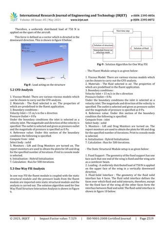
Fig-9 : Solution Algorithm for One Way FSI - The Fluent Module setup is as given below: 1. Viscous Model: There are various viscous models which can be chosen to carry out the CFD analysis. 2. Materials : The fluid selected is air. The properties of which are predefined in the fluent application. 3. Boundary conditions : Velocity Inlet = 15 m/s in the x direction Pressure Outlet = 0 Pa Under the boundary conditions the inlet is selected as a velocity inlet. The magnitude and direction of the velocity is specified. The outlet is selected and given as pressure outlet and the magnitude of pressure is specified as 0 Pa. 4. Reference value: Under this section of the boundary condition the following is specified. Compute from : inlet Select body : solid 5. Monitors : Lift and Drag Monitors are turned on. The report monitors are used to obtain the plots for lift and drag for the specified number of iterations. Print to console mode is selected. 6. Initialisation : Hybrid Initialization 7. Calculation : Run for 500 iterations.
Fig-8 : Load acting on the structure
5.2 CFD Analysis 1. Viscous Model: There are various viscous models which can be chosen to carry out the CFD analysis. 2. Materials : The fluid selected is air. The properties of which are predefined in the fluent application. 3. Boundary conditions : Velocity Inlet = 15 m/s in the x direction Pressure Outlet = 0 Pa Under the boundary conditions the inlet is selected as a velocity inlet. The magnitude and direction of the velocity is specified. The outlet is selected and given as pressure outlet and the magnitude of pressure is specified as 0 Pa. 4. Reference value: Under this section of the boundary condition the following is specified. Compute from : inlet Select body : solid 5. Monitors : Lift and Drag Monitors are turned on. The report monitors are used to obtain the plots for lift and drag for the specified number of iterations. Print to console mode is selected. 6. Initialisation : Hybrid Initialization 7. Calculation : Run for 500 iterations.
- The Static Structural Module setup is as given below: 1. Fixed Support : The geometry of the fixed support has one face such that one end of the wing is fixed and the wing acts as a cantilever beam. 2. Loading : A uniformly distributed load of 750 N is applied on the upper face of the wing in a vertically downward direction. 3. Fluid-Solid Interface : The geometry of the fluid solid interface has 4 faces. The fluid solid interface defines the faces over which fluid and solid interacts, therefore, except for the fixed face of the wing all the other faces form the interface between fluid and solid. The fluid-solid interface is shown in figure 10 below:
5.3 One Way FSI Analysis In one way FSI the fluent module is coupled with the static structural module and the pressure loads from the fluent module are imported onto static structural module and the analysis is carried out. The solution algorithm used for One Way Fluid Structure Interaction Analysis is shown in Figure 9.
© 2021, IRJET
|
Impact Factor value: 7.529
|
ISO 9001:2008 Certified Journal
|
Page 2519


