International Research Journal of Engineering and Technology (IRJET)
e-ISSN: 2395-0056
Volume: 08 Issue: 04 | Apr 2021
p-ISSN: 2395-0072
www.irjet.net
Adjustable Pull-Rod Suspension System Swaraj Kashid1, Gaurav Parate2, Gaurav Gaikwad3 ---------------------------------------------------------------------***---------------------------------------------------------------------
Abstract – The main criteria of this project was to design a
length-adjustable pull-rod for a double-wishbone pull-rod suspension for an FSAE automotive. Pull-rod suspension and push-rod suspension confer with a specialized kind of automotive suspension that is supported by a doublewishbone system. The modeling of components is finished in the SOLIDWORKS software system. Later, the structural analysis for the component was executed on ANSYS software system. This study helps to understand the stresses, strains, and total deformation which are focused on inbound areas. Also, the factor of safety is determined. These parameters can facilitate deciding if this component is safe for use. Key Words: Formula student, Pullrod analysis, Double wishbone suspension, ANSYS, Solidworks, Turnbuckle
Figure 1: Coupler
1. INTRODUCTION The function of an ideal suspension is to handle the bump, rebound, and load transfer forces in a dynamic state. And a pull-rod plays an important role in this. One end of the pullrod is mounted on the upper wishbone which points down towards the bell crank. Pull-rod is an assembly which when the vehicle goes over a bump pulls the mechanism downwards putting the pull-rod in tension, Pull-rod acts in the same direction of cornering load of outer wheel and hence transfers the motion to the damper. This keeps the mechanism stable and in contact with the ground. The length of the pull-rod designed in this project can easily be adjusted by a spanner without the need of actually disassembling it from the entire wheel assembly. The length of the pull-rod designed in this project can easily be adjusted by a spanner without the need of actually disassembling it from the entire suspension assembly. This project is done for the ease of manipulation of the pull rod's length while adjusting the weight distribution of the car.
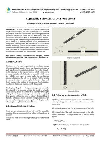
Figure 2: Billet
2.1. Following are the properties of Bolt: 1]Pitch (p): distance from a point on the screw thread to a corresponding point on the next thread measured parallel to the axis.
2. Design and Modeling of Pull-rod
2]Nominal Diameter (d): The largest diameter of the bolt.
These are the dimensions of the pull-rod. The assembly consists of three components, two billets at the end and a coupler.
2]Helix angle (α): The angle is the angle made by the helix of the thread with a plane perpendicular to the axis of the screw.
A coupler is made by assembling two hexagonal M8 bolts and a nut.
tanα= p/(π*dm) 3]Mean diameter (dm): Mean diameter is given by, dm = d- 0.5p
© 2021, IRJET
|
Impact Factor value: 7.529
|
ISO 9001:2008 Certified Journal
|
Page 3926