International Research Journal of Engineering and Technology (IRJET)
e-ISSN: 2395-0056
Volume: 08 Issue: 04 | Apr 2021
p-ISSN: 2395-0072
www.irjet.net
STRUCTURAL AND MODAL ANALYSIS OF WIND TURBINE BLADES Arjun Saxena K S Under Graduate Student, Dept. of Mechanical Engineering, Rajiv Gandhi Institute of Technology, Kottayam, Kerala, India ----------------------------------------------------------------------***---------------------------------------------------------------------
Abstract - Wind turbine blades are complex structures
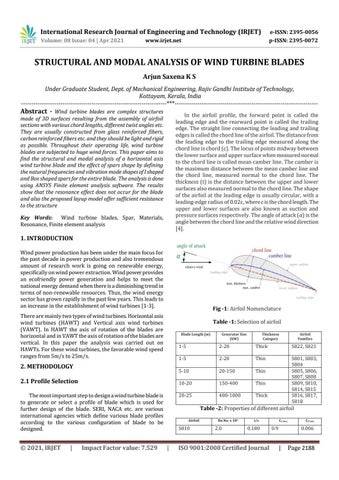
In the airfoil profile, the forward point is called the leading edge and the rearward point is called the trailing edge. The straight line connecting the leading and trailing edges is called the chord line of the airfoil. The distance from the leading edge to the trailing edge measured along the chord line is chord (c). The locus of points midway between the lower surface and upper surface when measured normal to the chord line is called mean camber line. The camber is the maximum distance between the mean camber line and the chord line, measured normal to the chord line. The thickness (t) is the distance between the upper and lower surfaces also measured normal to the chord line. The shape of the airfoil at the leading edge is usually circular, with a leading-edge radius of 0.02c, where c is the chord length. The upper and lower surfaces are also known as suction and pressure surfaces respectively. The angle of attack (α) is the angle between the chord line and the relative wind direction [4].
made of 3D surfaces resulting from the assembly of airfoil sections with various chord lengths, different twist angles etc. They are usually constructed from glass reinforced fibers, carbon reinforced fibers etc. and they should be light and rigid as possible. Throughout their operating life, wind turbine blades are subjected to huge wind forces. This paper aims to find the structural and modal analysis of a horizontal axis wind turbine blade and the effect of spars shape by defining the natural frequencies and vibration mode shapes of I shaped and Box shaped spars for the entire blade. The analysis is done using ANSYS Finite element analysis software. The results show that the resonance effect does not occur for the blade and also the proposed layup model offer sufficient resistance to the structure Key Words: Wind turbine blades, Spar, Materials, Resonance, Finite element analysis
1. INTRODUCTION Wind power production has been under the main focus for the past decade in power production and also tremendous amount of research work is going on renewable energy, specifically on wind power extraction. Wind power provides an ecofriendly power generation and helps to meet the national energy demand when there is a diminishing trend in terms of non-renewable resources. Thus, the wind energy sector has grown rapidly in the past few years. This leads to an increase in the establishment of wind turbines [1-3].
Fig -1: Airfoil Nomenclature
There are mainly two types of wind turbines. Horizontal axis wind turbines (HAWT) and Vertical axis wind turbines (VAWT). In HAWT the axis of rotation of the blades are horizontal and in VAWT the axis of rotation of the blades are vertical. In this paper the analysis was carried out on HAWTs. For these wind turbines, the favorable wind speed ranges from 5m/s to 25m/s.
Table -1: Selection of airfoil Blade Length (m)
2. METHODOLOGY 2.1 Profile Selection The most important step to design a wind turbine blade is to generate or select a profile of blade which is used for further design of the blade. SERI, NACA etc. are various international agencies which define various blade profiles according to the various configuration of blade to be designed.
© 2021, IRJET
|
Impact Factor value: 7.529
Generator Size (kW)
Thickness Category
Airfoil Families
1-5
2-20
Thick
S822, S823
1-5
2-20
Thin
5-10
20-150
Thin
10-20
150-400
Thin
20-25
400-1000
Thick
S801, S803, S804 S805, S806, S807, S808 S809, S810, S814, S815 S816, S817, S818
Table -2: Properties of different airfoil Airfoil
S810
|
Re.No. x 106
2.0
t/c
0.180
ISO 9001:2008 Certified Journal
CL max
0.9
CD min
0.006
|
Page 2188