International Research Journal of Engineering and Technology (IRJET)
e-ISSN: 2395-0056
Volume: 07 Issue: 09 | Sep 2020
p-ISSN: 2395-0072
www.irjet.net
Design and Implementation of Cable Analyser K.M. Dhanalakshmi1, R. Nehruji2, D. Rajesh3, M. Peer Mohamed4 1Associate
professor, Department of Electronics and Communication Engineering, S.A. Engineering College, Chennai 2,3,4U.G student, Department of Electronics and Communication Engineering, S.A. Engineering College, Chennai --------------------------------------------------------------------------***----------------------------------------------------------------------Abstract: This project is cable fault monitoring system, which is used to monitor the electrical problems in all three R, Y and B phases and also to locate the fault in the cable. The PC is connected to microcontroller through serial port; the microcontroller is also connected to R, Y, and B phases. From the front-end software, we check any over voltage, under voltage, over current phase-to-phase short, phase-to-neutral short has occurred. The cable tester implements the cable connectivity test by means of high- and low-level scanning. Analysing the cable various faults in single desk by identifying the problems using open circuit test/short circuit tests, sequence tests and shield grading. The above test will complete the task with duration of minimum 2 minutes and maximum 7 minutes based on the number of sockets/ports. Keywords: cable, electrical problems, fault monitoring. which finds the cables fault as well as to locate the fault in the cable. In order to improve the test efficiency there are many ways to find the cables fault using the below methods.
I. INTRODUCTION Locating cable faults can be quite challenging even though there are a number of fault location techniques and a few tools to help with underground cable faults. Most of these issues are due to technicians not properly interpreting the test results and then selecting the wrong tool for the task at hand, and ultimately a lot of wasted time is due to taking a shortcut in the process. The challenges of locating underground faults can be significantly minimized by understanding the available equipment and techniques. Education and cable fault position knowledge will help to correct and improve the understanding of the findings and will certainly help to correct and improve the range of which equipment and technique is most appropriate for a particular task. But only a high level of awareness will correct wasted time which is afforded by taking shortcuts.
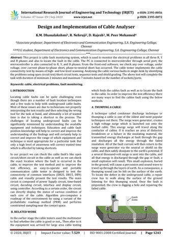
A. THUMPING A CABLE: A technique called condenser discharge technique or thumping a cable is one of the oldest and most popular techniques out there. The surge wave generator, creates a high voltage surge which is launched out onto the faulted cable. This energy surge will travel along the conductor of cables. If it reaches an area of dielectric breakdown or a failure in the insulating material, the transmitted energy discharges at fault through the gap and discharges all the energy through the failed insulation. All of the fault current will then return to the surge wave generator via the neutral or shield on the cable, and then safely dissipate to the earth's potential. If a several thousand-volt surge is sent into the cable, and all that energy is discharged through the gap or fault, a small explosion will result. This small explosion, buried in the ground, will cause a percussion and sound wave to travel up through the layers of earth. As a consequence, a thumping sound can be felt on the surface of the earth. To locate the defect in the underground cable, a repair crew has to walk along the surface of the ground listening for this thumping sound. Once the fault is pinpointed, the crew is digging a hole and repairing the failed cable.
In our project we can check the cable fault’s like open circuit/short circuit in the cable as well as we can check the exact location where the fault is occurred in the cable, to improve the test method and to improve the test efficiency, an easy-to-operate and portable communication cable tester is designed to test the connectivity of common interfaces (DB25, DB15, DB9) cable and visually present the test results. The main circuit is composed of power Supply circuit, time-based circuit, decoding circuit, interface and display circuit, using controller. According to a certain order, the circuit can directly display the status of various condition of each core of the cable. Algorithm pre-computes a roadmap of the environment by using a variant of the probabilistic roadmap method (PRM) and performs constrained sampling near the contact space. II. RELATED WORK In the earlier stage the cable testers used the multimeter to find whether the cable is good or not.,. Then after to it the equipment was arrived for large area cable testing
Š 2020, IRJET
|
Impact Factor value: 7.529
|
ISO 9001:2008 Certified Journal
|
Page 1243