International Research Journal of Engineering and Technology (IRJET)
e-ISSN: 2395-0056
Volume: 07 Issue: 08 | Aug 2020
p-ISSN: 2395-0072
www.irjet.net
Evaluation of Optimum Design Parameters for Connecting Rod using FEA Nikhil P. Patil1, Suhas M. Shinde2 1PG
Scholar, Jayawantrao Sawant College of Engineering, SPPU Pune-028, India Jayawantrao Sawant College of Engineering, SPPU Pune-028, India ---------------------------------------------------------------------***---------------------------------------------------------------------2Professor,
Abstract - The connecting rod connects the pistons to the
to combustion, to high tensile loads due to inertia. Therefore, durability of this component is of critical importance. Due to these factors, the connecting rod has been the topic of our project for different aspects such as life cycle, materials cost, fatigue, etc… For the current manufacturing condition, it was necessary to investigate finite element modelling techniques, optimization techniques, and developments in new materials, fatigue modelling, and material cost analysis for different mechanical components such as automobile, plastic, home appliances etc…, which are made by large volume production. Due to its large volume production, it is only logical that optimization of the connecting rod for its material cost will result in large-scale savings. Below is a picture of the fundamental parts of an engine. Surface "L" is where combustion occurs, air enters through "M", and "H" is the shaft through which power is accumulated and delivered out of the engine. The combustion occurs against the top surface of the piston (F) and pushes the connecting rod (G) downward, causing the shaft to move in a circular motion. So, it is easy to see that the connecting rod harnesses all of the power produced in combustion and converts it into something useful, in this case a spinning shaft.
crankshaft. It converts the linear motion of the pistons to the rotary motion of the crankshaft. On every stroke, the connecting rod is stretched and compressed. This force and additional loading may cause the connecting rod to break. The broken rod can go through the engine block completely, ruining the engine, this condition is known as "throwing a rod". The current work includes design of connecting rod with given conditions and CAD modelling of the connecting rod is done. The connecting rod is compared with four different materials 20CrMo steel alloy, AA7010, AA7068, AA6010 aluminum alloys. The best combination of parameters like Von-Misses Stress and Strain, deformations, Factor of safety were done in ANSYS programming. In this different materials are compared and AA7068 possess less weight and deformations. Aluminum Alloys are lesser in weight, corrosion resistance, non-toxic, flexible in design and stiffer than other material like Steel. ANSYS software was employed to analyze and examine the effect of stress in different parts of the connecting rod. For the analysis we have started with the existing design parameters and then incrementally changed the fillet radius at big end with keeping the small end dimensions constant and then changing the fillet radius of the small end with keeping the fillet radius of the big end intact. Finally optimum parameters were selected for the modified design for the minimum stress conditions. Key Words: Connecting Rod, Aluminum Alloy, Fillet radius, Pistons, Crankshaft, CAD modeling
1. INTRODUCTION Connecting rod is an integral component of internal combustion engine and it is classified under functional component. It acts as a linkage between piston and crank shaft. The main function of connecting rod is to transmit the translational motion of piston to rotational motion of crank shaft. The function of the connecting rod also involves transmitting the thrust of the piston to the connecting rod. Connecting rod has three main zones. The piston pin end, the center shank and the big end. The piston pin end is the small end, the crank end is the big end and the center shank is of Icross section. Connecting rod is a pin jointed strut in which more weight is concentrated towards the big end.
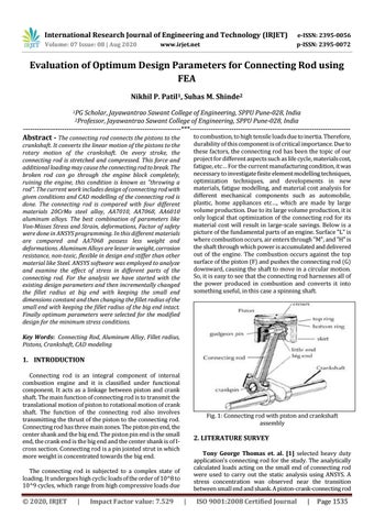
Fig. 1: Connecting rod with piston and crankshaft assembly
2. LITERATURE SURVEY Tony George Thomas et. al. [1] selected heavy duty application’s connecting rod for the study. The analytically calculated loads acting on the small end of connecting rod were used to carry out the static analysis using ANSYS. A stress concentration was observed near the transition between small end and shank. A piston-crank-connecting rod
The connecting rod is subjected to a complex state of loading. It undergoes high cyclic loads of the order of 10^8 to 10^9 cycles, which range from high compressive loads due
© 2020, IRJET
|
Impact Factor value: 7.529
|
ISO 9001:2008 Certified Journal
|
Page 1535