International Research Journal of Engineering and Technology (IRJET)
e-ISSN: 2395-0056
Volume: 07 Issue: 07 | July 2020
p-ISSN: 2395-0072
www.irjet.net
Design and Optimization of Hydraulic Cylinder Mounting Bracket Komal Sawant1, Sainand Jadhav2 1M.E.
Student, Department of Mechanical Engineering, NBN Sinhgad School of Engineering, Pune, India Department of Mechanical Engineering, NBN Sinhgad School of Engineering, Pune, India ---------------------------------------------------------------------***---------------------------------------------------------------------2Professor,
Abstract - In present study weight optimization, vibration
analysis is considered as a major factor to design an optimized model for the existing design of hydraulic cylinder mounting bracket. So, experimental and numerical analysis of existing hydraulic cylinder mounting bracket is to performed to study the effect of deformation, mode shapes, weight optimization and to obtain optimized model using ANSYS software (Topology optimization). Static structural and free vibration analysis are to be performed to determine best optimized model results with existing design. From the static structural analysis, total deformation, von Mises are to be calculated and natural frequencies are to be obtained from modal analysis. Results and conclusions will be drawn. Suitable future scope will be suggested.
cylinder bar likewise has mounting connections to interface the chamber to the item or machine segment that it is pushing or pulling. A water driven chamber is the actuator or "engine" side of this framework. The cylinder pushes the oil in the other chamber back to the supply. On the off chance that we accept that the oil enters from top end, during expansion stroke, and the oil pressure in the pole end/head end is around zero, the power F on the cylinder bar rises to the weight P in the chamber times the cylinder zone A. The welded chamber is essentially a barrel with a top welded to the base, and afterward with the mounting treatment welded to that top, commonly a cross cylinder or double tangs to imitate a clevis. The cylinder and pole are introduced into the chamber, and afterward a strung head is slid over the pole and torque onto the barrel.
Key Words: FEA, UTM, Topology optimization, Hydraulic bracket
1. INTRODUCTION Current advancements in the water power industry have reformed our capacity to mechanize forms in the horticultural, development, and assembling areas. To accomplish these advances, computerized machines must have pressure driven systems that can give exact and dependable movement control. Water driven systems can control both the rotational and straight movement used in these procedures. Water powered engines are utilized to actualize rotational movement, while direct control is performed by pressure driven chambers. Water driven chambers are accessible in an assortment of styles and can be mounted from multiple points of view. They are effective and dependable, and albeit little of their fundamental structure has changed altogether in ages, they are as yet pertinent to the ventures to which they provide food. Albeit a few chambers are made with a by and large poor form quality, for example, with cast iron tops and heads, greater chambers are normally built with produced steel. Water powered chambers get their capacity from pressurized water powered liquid, which is regularly oil. The water driven chamber comprises of a chamber barrel, in which a cylinder associated with a cylinder bar moves to and fro. The barrel is shut toward one side by the chamber base (likewise called the top) and the opposite end by the chamber head (additionally called the organ) where the cylinder bar comes out of the chamber. The cylinder has sliding rings and seals. The cylinder separates within the chamber into two chambers, the base chamber (top end) and the cylinder bar side chamber (bar end/head end). Ribs, trunnions, clevises, and drags are basic chamber mounting alternatives. The Š 2020, IRJET
|
Impact Factor value: 7.529
|
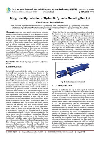
Fig -1: Hydraulic cylinder bracket
2. LITERATURE REVIEW Priyanka S. Dahaleaet al. [1] in this paper it presents experimental and Finite Element examination of a run of the mill motor mounting bracket. It likewise introduced the Modal Analysis in FEA to decide the frequency band and check the bracket for security. The exploratory examinations for co-connection to build up variety of rate and in this manner decide the idea of Boundary conditions to be utilized in FEA for progressively precise investigation. The Automobile motor case framework may encounter undesirable vibrations brought about by impedance between the street and the motor. Motor bracket has been planned as a structure to help motor. Because of vibrations of motor the openings on the motor Bracket get extended which prompts the failure of bracket. The outcomes got for the static basic and modular investigation have demonstrated that the subsequent limit condition for example one fixed and one pressure support are increasingly precise with less level of deviation 18.6 % with exploratory outcomes, which can be utilized for additional investigation for wellbeing of Engine mounting bracket. ISO 9001:2008 Certified Journal
|
Page 5441