International Research Journal of Engineering and Technology (IRJET)
e-ISSN: 2395-0056
Volume: 07 Issue: 07 | July 2020
p-ISSN: 2395-0072
www.irjet.net
IoT BASED CIRCUIT BREAKER Santosh Ashok Kamble1, Jayashri Shrirang Bhagwat2, Nilima Shrikrishna Bakde3 1Assitant
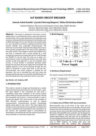
Professor, Electronics and Computer Science Dept. SAKEC, Mumbai 2Lecturer, Electronics Dept., Govt. Polytechnic, Karad. 3Lecturer, Electronics Dept., Govt. Polytechnic, Karad. ---------------------------------------------------------------------***---------------------------------------------------------------------2. Block Diagram Abstract - The project is designed to shut down a power supply when it is overloaded by using a super-fast electronic circuit breaker. The concept of electronic circuit breaker came into focus realizing that the conventional circuit breakers such as MCBs take longer time to trip. Therefore, for sensitive loads, it is very important to activate a tripping mechanism at the shortest possible time, preferably instantaneously. The electronic circuit breaker is based on the voltage drop across a series element proportional to the load current, typically a low-value resistor. This voltage is sensed and rectified to DC, and then is compared with a preset voltage by a level comparator to generate an output that drives a relay through the MOSFET to trip the load. The relay use in place of a semiconductor switch is preferred because such solid state switches would invariably fail in case of accidental short circuits. A circuit breaker is automatic operated switch designed to shut down the power supply when overloaded. The tripping depends on the current passing through the CTs which is connected in series with load. It uses the PICmicrocontroller into which program is dumped for the operation. The unit is extremely fast and over comes the drawback of thermal type circuit breaker like MCB based on a thermal bimetal lever-trip mechanism which is very slow.
3. Hardware Requirement The system consists of the following parts:
Key Words: IoT, Arduino, GSM
Sr. No.
Components
Quantity
1.
Arduino Uno(ATMEGA 328P
1
1. INTRODUCTION
microcontroller)
This article is aimed to design and demonstrate a simple password based superfast electronic circuit breaker + gsm. The input signals or the commands are sent from a transmitter using main computer or the centre location called a HUB, processed and used to drive the loads. At both the transmitter and receiver, a microcontroller is used to process the signals. The circuit works on the principle of GSM Wireless communication as well as manual communication. Communication involves transmitting signals using signal as the carrier. The input signal from switches is processed by the microcontroller, encoded by the encoder, modulated and transmitted by the transmitter. At the receiver, the modulated signal is demodulated by demodulator, decoded by the decoder and processed by the microcontroller to control the output load.
Š 2020, IRJET
|
Impact Factor value: 7.529
2.
GSM Module
1
3.
Relay
4
4.
LCD 16 X 2
1
5.
Adapter
1
TABLE I: Hardware requirements 3.1 Arduino Uno (ATMEGA 328P microcontroller): Microcontroller acts as the brain of the robot and its movement is decided by the microcontroller. We have used Arduino Uno microcontroller in our project. The Arduino Uno is an open-source microcontroller board based totally on the Microchip ATmega328P microcontroller and developed by Arduino.cc (Figure1). The board has units of digital and analog input/output (I/O) pins that can be interfaced to various enlargement boards and other circuits. The board has fourteen Digital input/output pins (out of which six can be used as PWM outputs), six Analog enter pins, and programmable with the Arduino IDE (Integrated
|
ISO 9001:2008 Certified Journal
|
Page 5261