International Research Journal of Engineering and Technology (IRJET) Volume: 07 Issue: 07 | July 2020 www.irjet.net
e-ISSN: 2395-0056 p-ISSN: 2395-0072
Design of Sinusoidal Pulse Width Modulation 3 Phase Bridge Inverter Vinay Kumar Pal1, Swati Singh2 1PG
Student [Power System], Dept. of EEE, Maharishi University of Information Technology, Lucknow, U.P., India 2Assistant Professor, Dept. of EEE, Maharishi University of Information Technology, Lucknow, U.P., India ---------------------------------------------------------------------***----------------------------------------------------------------------
Abstract - In this article, Pulse Width Modulation (PWM)
is designed using diode or thyristor to provide uncontrolled and controlled dc power, also said as unidirectional and bidirectional devices. Other than Adjustable Speed Drive (ASD); Switch Mode Power Supply (SMPS), DC power supply (for measurement and testing), Uninterrupted Power Supply (UPS), Battery charging set, Grid interface of Solar PV module, and etc. employs AC/DC conversion. Controlled device is advantageous as the input harmonics is less and power factor is higher as compared to uncontrolled, because of which used of heavy and costly line filters can be eliminated. These controlled device uses power switches like MOSFET, IGBT, GTO, etc. One of the best methods for speed control application is V/F control of induction motor, Pulse Width Modulation (PWM) or Sinusoidal Pulse Width Modulation (SPWM) can be use to provide the triggering pulse for both the converters with feedback control (in some applications)[3]. For more reliable operation and results filters can be used at the line side [8]. PWM gate pulse is designed with suitable modulation index; it will also give the required Total Harmonic Distortion (THD). By varying the modulation index (m) current and voltage harmonics can be varied [8]. rectifier. required pulse of triggering signal generator [1 ,4]. Output voltage from an inverter can also be adjusted by exercising a control within the inverter itself. The most efficient method of doing this is by pulse-width modulation control used within an inverter.
controlled 3-phase inverter for Renewable Energy (RES) Applications and environmental constraints are presented. The three-phase inverter with reduced components is realized in the solar PV applications. As the use of renewable energy sources are increased and will going to be increased to a large extend in future. Specially, solar energy will going to play a huge role as a major energy source. The output of the inverter is direct current, so an inverter becomes a critical component for the flow of electricity from solar modules to storage battery, loads and grids. A three phase voltage source inverter Sinusoidal Pulse Width Modulation based inverter is going to be utilized. High frequency carrier wave is compared with sinusoidal reference wave of desired frequency. The width of each pulse is varied in proportion to the amplitude of a sine wave called SPWM. The advantage of SPWM technique is that it reduces the harmonic contents of the output voltage compared to single pulse width modulation and multi-pulse modulation. The advantage of inverter with two stage three phase bipolar SPWM is good performance and efficiency as it doubles the switching frequency of inverter voltage and so the output filter becomes smaller, cheaper and easier to implement. Key Words: SPWM (Sinusoidal Pulse Width Modulation), PWM (Pulse Width Modulation), Induction motor, 3 phase bridge inverter.
1. INTRODUCTION Energy is the considered to be the pivotal input for DC-AC inverters have been widely used in industrial applications such as uninterruptible power supplies, static frequency changes and AC motor drives. Recently, the inverters are also playing important roles in renewable energy applications as they are used to link a photovoltaic or wind system to a power grid. Like DC-DC converters, the DC-AC inverters usually operate in a pulse width modulated (PWM) way and switch between a few different circuit topologies, which means that the inverter is a nonlinear, specifically piecewise smooth system. In addition, the control strategies used in the inverters are also similar to those in DC-DC converters. For instance, current-mode control and voltage-mode control are usually employed in practical applications. In the last decade, studies of complex behavior in switching power converters have gained increasingly more attention from both the academic community and industry[1-2]
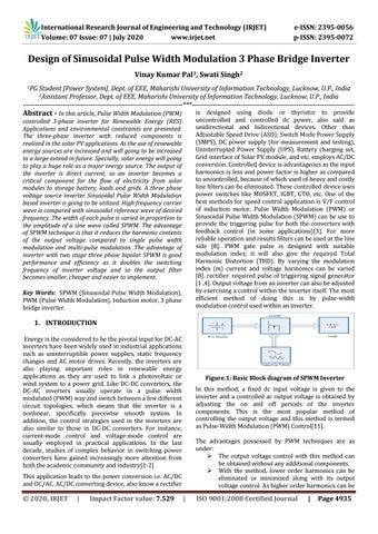
Figure.1: Basic Block diagram of SPWM Inverter In this method, a fixed dc input voltage is given to the inverter and a controlled ac output voltage is obtained by adjusting the on and off periods of the inverter components. This is the most popular method of controlling the output voltage and this method is termed as Pulse-Width Modulation (PWM) Control[11]. The advantages possessed by PWM techniques are as under: The output voltage control with this method can be obtained without any additional components. With the method, lower order harmonics can be eliminated or minimized along with its output voltage control. As higher order harmonics can be
This application leads to the power conversion i.e. AC/DC and DC/AC. AC/DC converting device, also know a rectifier
© 2020, IRJET
|
Impact Factor value: 7.529
|
ISO 9001:2008 Certified Journal
|
Page 4935