International Research Journal of Engineering and Technology (IRJET)
e-ISSN: 2395-0056
Volume: 07 Issue: 06 | June 2020
p-ISSN: 2395-0072
www.irjet.net
Open Loop Volts/Hertz Speed Control of Induction Motor with Voltage Fed Inverter M. NaliniDevi1, S. Sudharani2 1,2Assistant
Professor, Dept. of Electrical and Electronics Engineering, Mahatma Gandhi Institute of Technology, Telangana, India. ---------------------------------------------------------------------***---------------------------------------------------------------------
Abstract - Volts/hertz(V/f) control technique has evidenced to be the foremost versatile within the industries, Out of the assorted ways of dominant Induction motors. The general theme of implementing V/f control has been given high importance because of its simplicity. One in all the fundamental needs of this theme is that the PWM inverters. In this, the PWM inverters are sculptural and their outputs can control the speed of the Induction Motor drives. Open-loop V/f control of induction motor analysis is done.
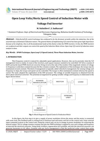
Key Words: SPWM Technique, Open Loop V/f Speed Control, Three Phase Induction Motor, Inverter 1. INTRODUCTION This Frequency control is natural for adjustable speed applications. However, this can be precisely what the V/f management tries to realize. In most of the inverters, each square measure needed to be controlled. V/F drive consists of IGBTs primarily based PWM electrical converter firing circuit at the side of the module. If the magnitude relation of voltage to frequency is unbroken constant because the flux remains constant. The exploitation of this technique, the torque may be maintained around constant. This kind of management is typically called volts/hertz management. By varying voltage and frequency in steps, the torque and speed can be controlled. The torque is often maintained constant whereas the speed is varied. The tactic adopted the exploitation of the DSP processor. The voltage at variable frequency is obtained from the three-phase electrical converter. The potential arrangement for getting variable voltage and frequency is elaborated in the figure shown below.
Fig -1: Block Diagram of Speed Control of Induction Motor In this figure, the first step is to give a supply of power modulator drives the motor and the motor is connected with some load. One feedback path is coming from in between load and motor and fed on the control unit. Some external input command is given to the control unit. Using the control unit, we try to change in power modulator for achieving the desired output. The dc voltage remains constant and also the PWM technique is applied to vary each voltage and frequency at intervals the electrical converter. Using diode rectifiers, regeneration isn't possible, and also the electrical converter can generate harmonics in AC offers. Constant volts per hertz management is that the preferred scalar control that varies
Š 2020, IRJET
|
Impact Factor value: 7.529
|
ISO 9001:2008 Certified Journal
|
Page 4497