International Research Journal of Engineering and Technology (IRJET)
e-ISSN: 2395-0056
Volume: 07 Issue: 06 | June 2020
p-ISSN: 2395-0072
www.irjet.net
Channel Estimation for Wireless Communication M. Arun Kumar1, M. Tejaswi Meenakshi2, M. Phani Pavan Kumar3, P. Kiran Kumar4, Ch.Sudha5, A. Akhil Sai Ranganath6. 1Faculty,
Dept. of ECE, D.M.S.S.V.H. College of Engineering, Machilipatnam, Andhra Pradesh, India. Final year students, Dept. of ECE, D.M.S.S.V.H. College of Engineering, Machilipatnam, Andhra Pradesh, India. ---------------------------------------------------------------------***--------------------------------------------------------------------modulation scheme employed on each sub-carrier. A total of Abstract – Proper knowledge about the system is N such symbols, Xm, are created. Then, the N symbols are prerequisite in any wired/wireless communication. mapped to bins of an Inverse Fast Fourier Transform (IFFT). Channel is either assumed or modeled or estimated in These IFFT bins correspond to the orthogonal sub-carriers in time domain/frequency domain. Frequency domain the OFDM symbol. Therefore, the OFDM symbol can be pilot aimed channel estimation techniques are either expressed as Least Square Error (LSE) based or Minimum Mean Square Error (MMSE) based. Least square based techniques are computationally less complex. Frequency domain channel estimation technique employ known symbols called pilots at known position Where the Xm is the baseband symbols on each sub-carrier, N in the Orthogonal Frequency Division Multiplexing is the no. of sub-carriers mapping the input stream into groups of log2 m where m is the size of each symbol. At the (OFDM) symbol grid these pilots are arranged in a receiver end, the discrete signal is demodulated using an regular manner as comb-type, block-type, 2D - grid N-point Fast Fourier Transform (FFT) operation. The type. 2,3,4,5,6B.Tech,
demodulated symbol stream is given by:
Key Words: LSE, MMSE, OFDM, SNR, BER.
1. INTRODUCTION In wired communication there is a physical connection between Transmitter and Receiver. Where as in wireless communication, the channel is “FREE SPACE”. The signal that is transmitted at the transmitter propagates in the free space where there will be many obstacles. So we need to know about the Channel State Information (CSI). As the demand for high data rate communication has been increasing rapidly, it is required to overcome the problems associated with high speed communications. As the transmission signal passes through the channel it gets effect by many degradations, such as noise attenuation, multipath, interference, time variation, nonlinearities. Time variant channel estimation is one such crucial technique used to improve the performance of the modern wireless system with Doppler shift and multipath spread.
Where, W(m) corresponds to the FFT of the samples of w(n), which is the Additive White Gaussian Noise (AWGN) introduced in the channel.
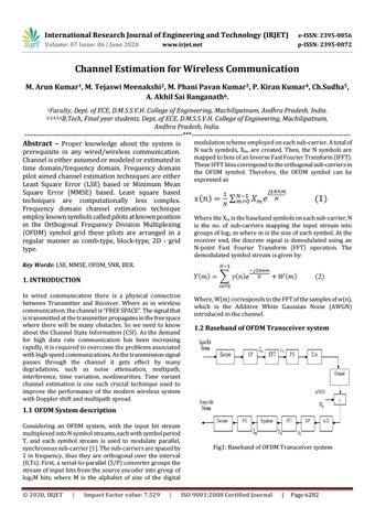
1.2 Baseband of OFDM Transceiver system
1.1 OFDM System description Considering an OFDM system, with the input bit stream multiplexed into N symbol streams, each with symbol period T, and each symbol stream is used to modulate parallel, synchronous sub-carrier [1]. The sub-carriers are spaced by 1 in frequency, thus they are orthogonal over the interval (0,Ts). First, a serial-to-parallel (S/P) converter groups the stream of input bits from the source encoder into group of log2M bits, where M is the alphabet of size of the digital © 2020, IRJET
|
Impact Factor value: 7.529
|
Fig1: Baseband of OFDM Transceiver system
ISO 9001:2008 Certified Journal
|
Page 6282