International Research Journal of Engineering and Technology (IRJET)
e-ISSN: 2395-0056
Volume: 07 Issue: 05 | May 2020
p-ISSN: 2395-0072
www.irjet.net
Voltage sensing and current sensing circuits sense the voltage level and current level through the circuit and sends the signal to the control. Feedback signals from the temperature sensor, voltage and current measurement are loaded to the controller to monitor the health of the converter. The gating pulses to the switches in the circuit is given by the gate driver circuit. DC-link capacitance of the dc-to-ac converter reduces the ripples. Controller used is of automotive standards with required number of GPIOs, ADCs, and DACs. It constantly monitors the overall operation of the system. Microcontroller has the CAN port that communicates with the BMS (Battery Management System) using CAN controller. The microcontroller provides the necessary control signals to the driver circuit based on the BMS output.
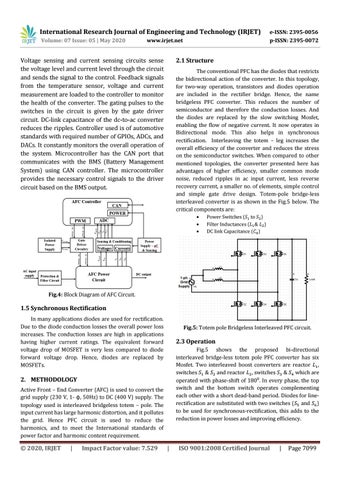
2.1 Structure The conventional PFC has the diodes that restricts the bidirectional action of the converter. In this topology, for two-way operation, transistors and diodes operation are included in the rectifier bridge. Hence, the name bridgeless PFC converter. This reduces the number of semiconductor and therefore the conduction losses. And the diodes are replaced by the slow switching Mosfet, enabling the flow of negative current. It now operates in Bidirectional mode. This also helps in synchronous rectification. Interleaving the totem – leg increases the overall efficiency of the converter and reduces the stress on the semiconductor switches. When compared to other mentioned topologies, the converter presented here has advantages of higher efficiency, smaller common mode noise, reduced ripples in ac input current, less reverse recovery current, a smaller no. of elements, simple control and simple gate drive design. Totem-pole bridge-less interleaved converter is as shown in the Fig.5 below. The critical components are:
Power Switches ( to ) Filter Inductances ( ) DC link Capacitance ( )
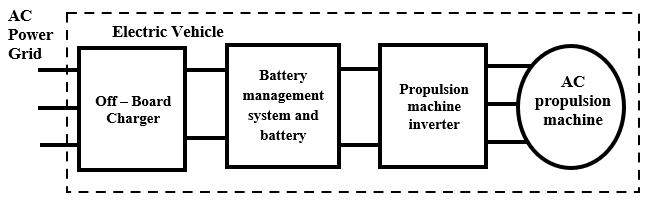
Fig.4: Block Diagram of AFC Circuit.
1.5 Synchronous Rectification In many applications diodes are used for rectification. Due to the diode conduction losses the overall power loss increases. The conduction losses are high in applications having higher current ratings. The equivalent forward voltage drop of MOSFET is very less compared to diode forward voltage drop. Hence, diodes are replaced by MOSFETs.
Fig.5: Totem pole Bridgeless Interleaved PFC circuit.
2.3 Operation Fig.5 shows the proposed bi-directional interleaved bridge-less totem pole PFC converter has six Mosfet. Two interleaved boost converters are reactor , switches & and reactor , switches & which are operated with phase-shift of 180⁰. In every phase, the top switch and the bottom switch operates complementing each other with a short dead-band period. Diodes for linerectification are substituted with two switches ( and ) to be used for synchronous-rectification, this adds to the reduction in power losses and improving efficiency.
2. METHODOLOGY Active Front – End Converter (AFC) is used to convert the grid supply (230 V, 1- ϕ, 50Hz) to DC (400 V) supply. The topology used is interleaved bridgeless totem – pole. The input current has large harmonic distortion, and it pollutes the grid. Hence PFC circuit is used to reduce the harmonics, and to meet the International standards of power factor and harmonic content requirement.
© 2020, IRJET
|
Impact Factor value: 7.529
|
ISO 9001:2008 Certified Journal
|
Page 7099