
3 minute read
5 Synchronous Rectification


International Research Journal of Engineering and Technology (IRJET) Volume: 07 Issue: 05 | May 2020 www.irjet.net e-ISSN: 2395-0056 p-ISSN: 2395-0072
1.1 On-Board Charger
Advertisement
On-board charger is a part of the EV, as depicted in the Fig.2. It allows charging at every placepossible as long as the supply, either 1-phor 3-ph, is available. The use of the OBC improves the charging convenience of the vehicle. The main disadvantage of this structure is additional DCto-AC inverter is required.
Fig.2: GeneralBlockDiagram of OBC.
1.2 Block Diagram of OBC
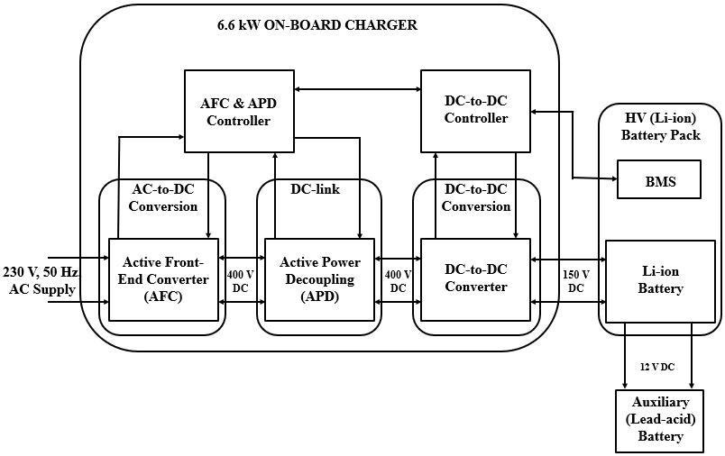
The main objective of the OBC is to charge-up the traction battery. OBC architecture proposed for the electric vehicles is shown in Fig.3. The on-board charger is made of three functional modules.
Fig.3: Block Diagram of Proposed OBC forEV. The OBC is designed to serve the following functions: Converting AC quantities from the grid into DC quantitiesthat charges the vehicle’s battery. Providing power factor correction (PFC) to shape the input current to a power supply, maximizing efficiency and reducing harmonics. Adjusting the produced DC voltage up or down to provide the correct DC levels to the battery. Auxiliary battery is charged from the main battery for the auxiliary loads in the electric vehicle.
1.3 Active Front-End Converter
On-Board Battery Chargers (OBC) actually have three important modules, they are Active Front-end Converters (AFC), Active Power Decoupling (APD) Circuit, and a dc-todc converter. Active Front-end Converter converts ac-todc or vice versa. Typically, inplug-in electric vehicle (PEV), a 1-ph PFC bridge converter is implemented as first stage of OBC, then an isolated dc-to-dc converter as the next stage [3]. But by the use of conventional circuits efficiency isless. Then,the most generallyemployedconverter in an OBC is a 1-ph diode-bridge ac-to-dc converter circuit followed by a dc-to-dcconverter. It altersthe 1-phgrid ac quantitiesto a regulated dcvoltage [4]. But the converters used were unidirectional that serves from grid to vehicle only. Semi-boost bridgeless PFC converter were used, which were slightly modified to operation in vehicle to grid mode. And it also reduced the common mode noise. But each bridge had to bear the maximum input current, leads to increase in the dimensionsandtherebycost of the components [5]. A bi-directional bridge-less totem-pole interleaved PFC converter by means of MOSFETs as first step of an OBC for EVs is proposed in this project. The projected converter offers bi-directional operation, permitting both G2V mode and V2G auxiliary services. This converter is appropriate for effective bi-directional on-board charging due to its advantages with respect to bi-directional action, reduced current ripple, lesser EMI, low switchinglosses and conduction losses [6].
The output of this active front end converter is desired to be with less ripple which is then utilized by the converter for further operation of OBC. The converter which converts AC power supply to the DC power supply is called as rectifier. The most commonly used rectifier is the diode bridge rectifier. One of the major concerns about selecting the topology of the rectifier is the harmonic in the line currents due to the source inductance. These harmonic components are responsible for the distortion of the voltage at the point of common coupling and produce undesirable effects. Due to which power factor becomes worst. Hence Power Factor Correction (PFC) is implemented using parallel switching devices, interleaved PFC, and bridgeless PFC that provides even higher efficiency.
1.4 Block Diagram of AFC
AFC converts the AC power supply to the DC supply as required by the battery. AFC has a controller that controls the circuit operation. Fig.4 show the high-level block diagram of AFC circuit.
