International Research Journal of Engineering and Technology (IRJET)
e-ISSN: 2395-0056
Volume: 06 Issue: 08 | Aug 2019
p-ISSN: 2395-0072
www.irjet.net
Improving Performance of Circularly Polarized Patch Antenna by Varying Stub Positions Gulshanpreet Singh1, Sehaj Rattan Singh2, Kuldeep Singh3 1Student,
Department of Electronics & Communication Engineering, University Institute of Engineering and Technology, Panjab University, Chandigarh, India 2Student, Department of Electrical & Electronics Engineering, University Institute of Engineering and Technology, Panjab University, Chandigarh, India 3Assistant Professor, Department of Electrical and Electronics Engineering, University Institute of Engineering and Technology, Panjab University, Chandigarh, India ---------------------------------------------------------------------***----------------------------------------------------------------------
Abstract - In this paper, we analysed the stacked
microstrip planar antenna and improved its performance by implementing circular polarization through change in stub position. Circular polarization is necessary to have constant receiving power levels. In order to create circularly polarized radiation, it is required to excite two orthogonal patch modes on the antenna with 90° phase difference. The extent of improvement is measured through some parameters like return loss, axial ratio and radiation efficiency of antenna using IE3D software.
overcome this problem. We have used the method of stacked microstrip patch as shown below (Figure 2):
Key Words: Axial ratio, Circular polarization, Return Loss, Radiation efficiency, Stub, Bandwidth
1. INTRODUCTION A three layer stacked microstrip planner antenna with air sandwiched in them is used. The outer layers are equally thick and have the same dielectric constant. Circular polarization [1] can be obtained by a number of methods [2] such as: 1. 2. 3. 4. 5.
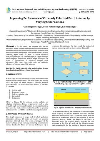
Fig-1: (a) 3-db hybrid (b) Truncated corner (c) Stub on radiating edge (d) corner fed (e) Slot centre
3-dB hybrid Truncated corner Stub on radiating edge Corner fed Slot centre
(Refer to Figure 1). An antenna mostly radiates an elliptical polarization defined by parameters such as axial ratio, tilt angle and sense of rotation. In our experiment we have used the Stub position method in order to generate unity axial ratio i.e.0 dB for a perfect circular polarization.
Fig-2: A patch antenna in a three layers dielectric
The simple structure of single-feed circularly polarized microstrip antennas [3] does not require an external polarizer. Although this offer some advantages but the main weakness of an ordinary microstrip antenna is its narrow bandwidth. There are several techniques [4] to
The stacked microstrip patch method for the multilayer (three Layers) microstrip antenna structure involves addition of a superstrate layer [5] over the patch. With the addition of superstrate, effective permittivity of all the substrate reduces. Hence, the length of the patch is decreased than the original length required for the resonance at 2.4 GHz. We will use the following quasistatic equation [6] for the multilayer dielectric structure
Š 2019, IRJET
ISO 9001:2008 Certified Journal
2. PROPOSED ANTENNA DESIGN
|
Impact Factor value: 7.34
|
|
Page 1270