International Research Journal of Engineering and Technology (IRJET)
e-ISSN: 2395-0056
Volume: 06 Issue: 04 | Apr 2019
p-ISSN: 2395-0072
www.irjet.net
DESIGN AND ANALYSIS OF HYDRAULIC CONTINUOUSLY VARIABLE TRANSMISSION Prof. R.K. Kawade1, Nikhil Patil2, Soham Mulik3, Sarvesh Patil4, Sagar Patil5 1Associate
Professor, Dr. D. Y. Patil Institute of Technology, Pune, India. 2Student & Nigdi, pune 3Student & Pimpri, pune 4Student & Sangvi, pune 5Student & Akurdi, pune
----------------------------------------------------------------***---------------------------------------------------------------
Abstract - New regulations enacted by Indian Government for emission and fuel economy has encouraged the development of Continuously variable transmission as a key technology for improving fuel efficiency with infinite gear ratio within specified range to attain optimum performance.CTV provides better gas mileage and acceleration, as it runs at the most efficient number revolutions per minute for given vehicle speed.
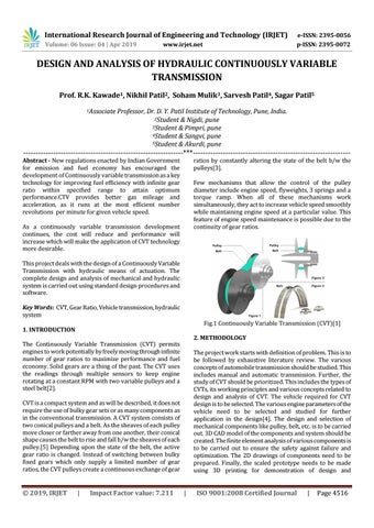
ratios by constantly altering the state of the belt b/w the pulleys[3]. Few mechanisms that allow the control of the pulley diameter include engine speed, flyweights, 3 springs and a torque ramp. When all of these mechanisms work simultaneously, they act to increase vehicle speed smoothly while maintaining engine speed at a particular value. This feature of engine speed maintenance is possible due to the continuity of gear ratios.
As a continuously variable transmission development continues, the cost will reduce and performance will increase which will make the application of CVT technology more desirable. This project deals with the design of a Continuously Variable Transmission with hydraulic means of actuation. The complete design and analysis of mechanical and hydraulic system is carried out using standard design procedures and software. Key Words: CVT, Gear Ratio, Vehicle transmission, hydraulic system
Fig.1 Continuously Variable Transmission (CVT)[1]
1. INTRODUCTION
2. METHODOLOGY
The Continuously Variable Transmission (CVT) permits engines to work potentially by freely moving through infinite number of gear ratios to maximize performance and fuel economy. Solid gears are a thing of the past. The CVT uses the readings through multiple sensors to keep engine rotating at a constant RPM with two variable pulleys and a steel belt[2].
The project work starts with definition of problem. This is to be followed by exhaustive literature review. The various concepts of automobile transmission should be studied. This includes manual and automatic transmission. Further, the study of CVT should be prioritized. This includes the types of CVTs, its working principles and various concepts related to design and analysis of CVT. The vehicle required for CVT design is to be selected. The various engine parameters of the vehicle need to be selected and studied for further application in the design[4]. The design and selection of mechanical components like pulley, belt, etc. is to be carried out. 3D CAD model of the components and system should be created. The finite element analysis of various components is to be carried out to ensure the safety against failure and optimization. The 2D drawings of components need to be prepared. Finally, the scaled prototype needs to be made using 3D printing for demonstration of design and
CVT is a compact system and as will be described, it does not require the use of bulky gear sets or as many components as in the conventional transmission. A CVT system consists of two conical pulleys and a belt. As the sheaves of each pulley move closer or farther away from one another, their conical shape causes the belt to rise and fall b/w the sheaves of each pulley.[5] Depending upon the state of the belt, the active gear ratio is changed. Instead of switching between bulky fixed gears which only supply a limited number of gear ratios, the CVT pulleys create a continuous exchange of gear
Š 2019, IRJET
|
Impact Factor value: 7.211
|
ISO 9001:2008 Certified Journal
|
Page 4516