International Research Journal of Engineering and Technology (IRJET)
e-ISSN: 2395-0056
Volume: 06 Issue: 04 | Apr 2019
p-ISSN: 2395-0072
www.irjet.net
Modeling of Retaining Wall for Surveillance under the Sensors Deep Sampat1, Prof. Girish Joshi2 1M.Tech
Student, G. H. Raisoni College of Engineering and Management, Pune, India Dept. of Civil Engineering, G. H. Raisoni College of Engineering and Management, Pune, India ---------------------------------------------------------------------***---------------------------------------------------------------------2Professor,
Abstract – Retaining wall is considered as one of
deflection is calculated. After calculating the deflection for failure the sensors are set according to the limits and if the limits are exceeds the alert is issued. Infrared sensors are used for the surveillance purpose
important structure and by the growing technology it has been a necessity to upgrade in terms the monitoring and the surveillance of the retaining wall using sensors. In the falling paper a model or a prototype of a cantilever retaining wall is made and is acted by the soil load the soil is dry soil. According to the calculation made the model has been made and then practically checked with the sensors mounting on the retaining wall.
Development of Model While making the model parameters were considered of a real retaining wall. The parameters were as follows, the height of the wall was considered as 4m. Then from the calculations the other dimensions were, the thickness of the stem was 200mm, the length of the base slab was 2.8m the length of the toe slab was 1.2m and heel slab is 1.4m the thickness of the base slab is 0.6m. This is the dimensions of the original retaining wall; from the above dimensions after carrying the dimensional analysis the prototype of the model was constructed. The model is constructed in mild steel. The dimension of the prototype is, 0.25m is the height of the wall, followed by the thickness is 1.62mm; the length of the base slab is 0.17m.
Key Words: Retaining wall, sensors, Model, Monitoring, Dry soil.
1. INTRODUCTION Retaining walls are moderately inflexible walls utilized for supporting the dirt mass along the side with the goal that the dirt can be held at various dimensions on the two sides. Retaining walls are structures intended to control soil to a slant that it would not normally keep to commonly a lofty, close vertical or vertical incline. The use is to bound soils between two distinct heights frequently in regions of various territory having bothersome inclines or in zones where the scene should be formed extremely and intended for increasingly explicit purposes like slope cultivating or roadway bridges. Retaining wall is one of most essential retaining structure yet as of late there have been many gripes going ahead the failure of the wall. So it has been important to keep up and keep observation on the strength of the structure. The fundamental burden following up on this structure is the sidelong earth weight which is otherwise called the earth pressure. The most essential thought in legitimate plan and establishment of retaining walls is to perceive and check the inclination of the held material to move down slant because of gravity. This makes parallel earth pressure behind the wall which relies upon the point of inward grating and the strong quality of the held material, just as the bearing and greatness of development the retaining structure experiences. The research work presents the monitoring and the surveillance of the retaining wall with use of sensors. The complete surveillance of the retaining wall is done considering the soil. In the following paper the soil type which has been considered is dry soil. The soil is then applied which surcharge ranging from zero to hundred kilo Newton based on the Rankine theory the load acting on the retaining wall is calculated on the basis of the load acting on the retaining wall the retaining wall is considered as a cantilever beam and then the maximum
Š 2019, IRJET
|
Impact Factor value: 7.211
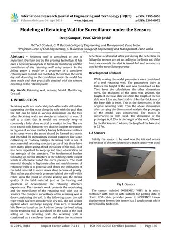
1.2 Sensors Initally the sensor to be used was the infrared sensor but because of the precision issue a made sensor was used.
Fig 1- Sensors The sensor included NODEMCU WIFI: it is micro controller with built in wifi, suitable for posting data to cloud. USB cable: provides power to NODEMCU. Linear displacement Sensor: this sensor has 5 touch points which are sensed by NodeMCU.
|
ISO 9001:2008 Certified Journal
|
Page 180