International Research Journal of Engineering and Technology (IRJET)
e-ISSN: 2395-0056
Volume: 06 Issue: 04 | Apr 2019
p-ISSN: 2395-0072
www.irjet.net
Modelling and CFD Simulation of Prototype of AC Plant Chiller onBoard Marine Ship Amolkumar Musale1, Pravin Hadgekar2 1M.Tech
Student, Dept. of Mechanical Engineering, Defence Institute of Advanced Technology, Pune, MH India professor, Dept. of Mechanical Engineering, Defence Institute of Advanced Technology, Pune, MH India ---------------------------------------------------------------------***---------------------------------------------------------------------2Assistant
Abstract - In present day shell and tube heat exchanger
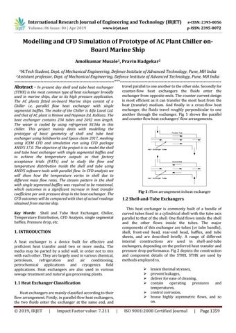
travel parallel to one another to the other side. Secondly for counter-flow heat exchangers the fluids enter the exchanger from opposite ends. The counter current design is most efficient as it can transfer the most heat from the heat (transfer) medium. And finally in a cross-flow heat exchanger, the fluids travel roughly perpendicular to one another through the exchanger. Fig 1 shows the parallel and counter flow heat exchangers’ flow arrangements.
(STHX) is the most common type of heat exchanger broadly used in marine ships, due to its high pressure application. The AC plants fitted on-board Marine ships consist of a Chiller i.e. parallel flow heat exchanger with single segmental baffles. The make of the Chiller is Alfa Laval Ltd. and that of AC plant is Heinen and Hopman ltd. Kolkata. The heat exchanger contains 234 tubes and 2692 mm length. The water is cooled by using refrigerant R134a in this chiller. This project mainly deals with modelling the prototype of basic geometry of shell and tube heat exchanger using Solidworks and Space claim 2017, meshing using ICEM CFD and simulation run using CFD package ANSYS 17.0. The objective of the project is to model the shell and tube heat exchanger with single segmental baffles and to achieve the temperature outputs as that factory acceptance trials (FATs) and to study the flow and temperature distribution inside the shell and tube using ANSYS software tools with parallel flow. In CFD analysis we will show how the temperature varies in shell due to different mass flow rates. The stream pattern in the shell with single segmental baffles was required to be rotational, which outcomes in a significant increase in heat transfer coefficient per unit pressure drop in the heat exchanger. The CFD outcomes will be compared with that of actual readings obtained from marine ship.
Fig-1: Flow arrangement in heat exchanger
1.2 Shell-and-Tube Exchangers This heat exchanger is commonly built of a bundle of curved tubes fixed in a cylindrical shell with the tube axis parallel to that of the shell. One fluid flows inside the shell and the other flows inside the tubes. The major components of this exchanger are tubes (or tube bundle), shell, front-end head, rear-end head, baffles, and tube sheets, and are described briefly. A range of different internal constructions are used in shell-and-tube exchangers, depending on the preferred heat transfer and pressure drop performance. Fig 2 depicts the construction and component details of the STHX. STHX are used by methods employed to,
Key Words: Shell and Tube Heat Exchanger, Chiller, Temperature Distribution, CFD Analysis, single segmental baffles, Pressure drop, etc.
1. INTRODUCTION A heat exchanger is a device built for effective and proficient heat transfer amid two or more media. The media may be parted by a solid wall, in order not to mix with each other. They are largely used in various chemical, petroleum, refrigeration and air conditioning, petrochemical applications and cryogenics field applications. Heat exchangers are also used in various sewage treatment and natural gas processing plants.
1.1 Heat Exchanger Classification
Heat exchangers are mainly classified according to their flow arrangement. Firstly, in parallel-flow heat exchangers, the two fluids enter the exchanger at the same end, and
© 2019, IRJET
|
Impact Factor value: 7.211
|
lessen thermal stresses, prevent leakages, deliver for ease of cleaning, contain operating pressures and temperatures, control corrosion, house highly asymmetric flows, and so on.
ISO 9001:2008 Certified Journal
|
Page 1359