International Research Journal of Engineering and Technology (IRJET) Volume: 06 Issue: 04 | Apr 2019 www.irjet.net
e-ISSN: 2395-0056 p-ISSN: 2395-0072
Extract Circular Object by tracing Region Boundary and using Circularity Measure P. Ummul Riswana M. phil., Computer Science Rani Anna Government College for women Tirunelveli, Tamil Nadu, India -----------------------------------------------------------------***-------------------------------------------------------------manipulate region information using boundary. These properties will make boundaries an attractive and economical representative of objects in shape analysis.
Abstract - Circularity measurement is defined as to
explain how close an object should be a true circle. It is called roundness. Circularity measurement is a 2Dimensional tolerance that it controls the overall form of a circle ensures it is not too oblong, square, or out of round. Circularity measurement essentially make a cross section of a cylindrical or round feature, and it also determines if the circle formed in that cross section is round object. Circularity measurement specifies the form of the surface in a specific area it needs to be considered when it calculates a statistical tolerance stack. It will skew the statistical tolerance slightly deeper, and it should be considered since parts are rarely perfectly circular. It focuses on the design of effective method that computes measurement of circularity of a part of a digital boundary. An existing circularity measurement of a set of discrete points, which was used in computational methodology, was extended to the case of part of digital boundary. From a single digital boundary, two set of points is extracted so that the measurement of circularity computed from these sets is representative of the circularity of digital boundary. So, the computation consists of two steps. First step is defined as the inner and outer sets of points are extracted from the input part of a digital boundary using digital geometry tools. Next step is defined as the measurement of circularity of these sets is computed by using classical tools from computational geometry. In this paper It find a circular object to trace region boundary using circularity.
2. BOUNDARY TRACING
Boundary-based techniques and thus Boundary descriptors are used in wide range of applications. The boundary descriptors require an ordered set of connected pixels (in clockwise or anticlockwise sense) which define the boundary of the object. The process of obtaining an ordered set of boundary pixels is known as boundary tracing or following. We will restrict ourselves to boundary tracing in binary images. It explicitly states the ambiguity in boundary tracing depending on starting pixel and the direction chosen for first step.
Key Words: Object detection, Identifying round object, Detect circular object, Region boundary, Trace boundary.
1. INTRODUCTION
Shape is a powerful visual cure for recognizing objects in images, segmenting images into regions corresponding to individual objects. To exploit circularity information, so detect boundary information for image. In image processing a digital binary image can consist of only two types of pixels, first pixel is the region pixels and the second pixel is background pixels. The region pixels will essentially capture the information about object. The boundary pixels are the region pixels; it is defined by their connectivity with the background pixels. In a digital binary image the number of boundary pixels is far less as compared to the region pixels. However, the boundary pixels capture the information about extent and geometry of the region concisely. It is more efficient to
© 2019, IRJET
|
Impact Factor value: 7.211
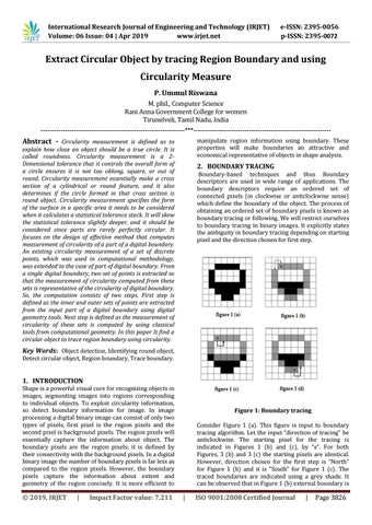
Figure 1: Boundary tracing Consider Figure 1 (a). This figure is input to boundary tracing algorithm. Let the input “direction of tracing” be anticlockwise. The starting pixel for the tracing is indicated in Figures 1 (b) and (c), by “s”. For both Figures, 3 (b) and 3 (c) the starting pixels are identical. However, direction chosen for the first step is “North” for Figure 1 (b) and it is “South” for Figure 1 (c). The traced boundaries are indicated using a grey shade. It can be observed that in Figure 1 (b) external boundary is
|
ISO 9001:2008 Certified Journal
|
Page 3826