International Research Journal of Engineering and Technology (IRJET)
e-ISSN: 2395-0056
Volume: 06 Issue: 03 | Mar 2019
p-ISSN: 2395-0072
www.irjet.net
DESIGN OF MID-BAND FREQUENCY PATCH ANTENNA FOR 5G APPLICATIONS HARINI. D1, JAGADESHWAR. V2, MOHANAPRIYA. E3, SHERIBA. T.S4 1,2,3Student,
Dept. of ECE Engineering, Valliammai Engineering College, Tamil Nadu, India Dept. of ECE Engineering, Valliammai Engineering College, Tamil Nadu, ---------------------------------------------------------------------***---------------------------------------------------------------------4Professor,
Abstract – The purpose of the paper is to investigate the design of rectangular patch antenna array fed by microstrip line at 5.2GHz for 5G applications. Our objective is to design a two element antenna array with bandwidth of about 1GHz and maximum radiation gain. The performance of rectangular 2*1 patch antenna array designed on FR-4 was analyzed. We obtain for topology of 2*1 rectangular array patch array antenna a bandwidth of 1 GHz respectively with almost similar gain of the order of 6 dBi.
antenna array at 5.2 GHz for WLAN, WiMax and Wi-Fi applications. First, we will describe the design of the rectangular patch antenna at 5.2 GHz which is necessary to calculate radiation parameters of the antenna (return loss, radiation pattern, gain).Finally we will show the simulation results of the return loss for the optimal position of the microstrip line feed for the rectangular patch antenna array. 1.1 ATENNA THEORY
Keywords - component; 5G applications; microstrip line; patch array antenna
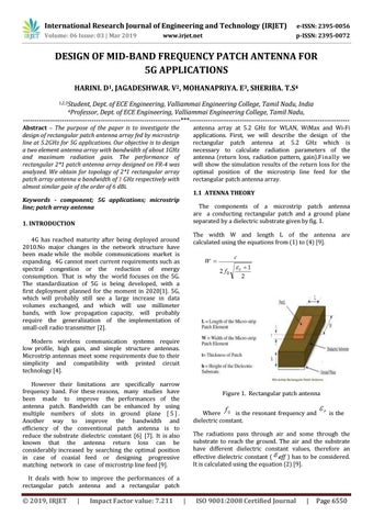
The components of a microstrip patch antenna are a conducting rectangular patch and a ground plane separated by a dielectric substrate given by fig. 1.
1. INTRODUCTION
The width W and length L of the antenna are calculated using the equations from (1) to (4) [9].
4G has reached maturity after being deployed around 2010.No major changes in the network structure have been made while the mobile communications market is expanding. 4G cannot meet current requirements such as spectral congestion or the reduction of energy consumption. That is why the world focuses on the 5G. The standardization of 5G is being developed, with a first deployment planned for the moment in 2020[1]. 5G, which will probably still see a large increase in data volumes exchanged, and which will use millimeter bands, with low propagation capacity, will probably require the generalization of the implementation of small-cell radio transmitter [2]. Modern wireless communication systems require low profile, high gain, and simple structure antennas. Microstrip antennas meet some requirements due to their simplicity and compatibility with printed circuit technology [4]. However their limitations are specifically narrow frequency band. For these reasons, many studies have been made to improve the performances of the antenna patch. Bandwidth can be enhanced by using multiple numbers of slots in ground plane [ 5 ] . Another way to improve the bandwidth and efficiency of the conventional patch antenna is to reduce the substrate dielectric constant [6] [7]. It is also known that the antenna return loss can be considerably increased by searching the optimal position in case of coaxial feed or designing progressive matching network in case of microstrip line feed [9].
Figure 1. Rectangular patch antenna Where is the resonant frequency and dielectric constant.
is the
The radiations pass through air and some through the substrate to reach the ground. The air and the substrate have different dielectric constant values, therefore an effective dielectric constant ( eff ) has to be considered. It is calculated using the equation (2) [9].
It deals with how to improve the performances of a rectangular patch antenna and a rectangular patch
Š 2019, IRJET
|
Impact Factor value: 7.211
|
ISO 9001:2008 Certified Journal
|
Page 6550