International Research Journal of Engineering and Technology (IRJET)
e-ISSN: 2395-0056
Volume: 06 Issue: 03 | Mar 2019
p-ISSN: 2395-0072
www.irjet.net
Analysis & Testing of Vortex Tube by Optimization of Material Shubham Chhajed1, Pankaj Moralwar2, Omkar Patil3, Rohit Patil4, Subhash Kumar5 1,2,3,4Department
of Mechanical Engineering, GHRCEM, Pune, Maharashtra, Guide, Department of Mechanical Engineering, GHRCEM, Pune Maharashtra. ---------------------------------------------------------------------***--------------------------------------------------------------------5Internal
Abstract - The vortex tube is a simple device, having no moving parts, which produces hot and cold air streams simultaneously at its two ends from a source of compressed air. It is a mechanical device with no moving parts. As such there is no theory so perfect, which gives the satisfactory explanation of the vortex tube phenomenon as explained by various researchers. Therefore, it was thought to perform experimentation. So we increase efficiency of such vortex tube for industrial spot cooling, process Cooling, Weld Cooling etc. The experiment results indicated that these modifications could remarkably improve the performance of vortex tube. effort have been made to get maximum output in terms of C.O.P. This paper focused analysis of cooling and heating effect temperature difference and C.O.P with different working condition.
A low cost, reliable, maintenance-free and compact size solution to a variety of industrial spot cooling problems. Using an ordinary supply of compressed air as a power source, vortex tubes create two streams of air, one hot and one cold, with no moving parts. Compressed air, normally 80-100 PSlG (5.5 - 6.9 Bar), is ejected tangentially through a generator into the vortex spin chamber. At up to 1,000,000 RPM, this air stream revolves toward the hot end where some escapes through the control valve. The remaining air, still spinning, is forced back through the center of this outer vortex. The inner stream gives off kinetic energy in the form of heat to the outer stream and exits the vortex tube as cold air. The outer stream exits the opposite end as hot air.
2. LITERATURE REVIEW
Key Words: Hot & Cold Air, Cooling & Heating Effect,
In 2012, Yunpeng Xue, Maziar Arjomandi and Richard Kelso [1]. This Paper presents detailed measurements of the flow properties inside a counter-flow vortex tube. The three dimensional velocity distributions inside the vortex tube lead to a new understanding of the flow behavior in the vortex tube. It is noted that in the central region of the tube, the irrotational vortex at the hot end was transformed to a forced vortex near the injection and kinetic energy is only transferred outwards from the hot end to the cold end.
Temperature Difference, L/D Ratio 1. INTRODUCTION
The vortex tube is device which generates separated flows of cold and hot gases from single compressed gas source. The vortex tube was invented quite by accident in 1933 by George Ranque & later developed by Hilsch (1947).
In 2017, R C Venkatesh, S Vishal, N Arun kumar [2] Performance evaluation of the Ranque, Hilsch vortex tube has been carried out theoretically. There is a value of cold mass fraction at which vortex tube has the highest temperature drop for all the given pressures at the L/D ratio of 17.5. The maximum cold end temperature drop is obtained at cold mass fraction of 60%. For the given L/D ratio, as the gas pressure increases, cold end temperature difference increases but the optimum value of cold mass fraction remains same.
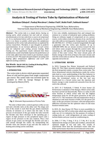
Fig -1: Schematic Representation of Vortex Tube The tube is fitted with a central aperture orifice at one end and a throttle valve at the other end. The shape and size of the nozzle is such that the gas attains maximum velocity of emission as it enters into the tube. In the process of movement of the gas inside the tube towards the throttle end, there develops in the spiraling gas a region of high pressure in the peripheral layers and a region of low pressure in the axis rotation. Thus a hot stream of gas comes out through the throttle end and a cold stream through the orifice. By manipulating the throttle valve, the amount of gas and also the extent of heating and cooling can be controlled.
Š 2019, IRJET
|
Impact Factor value: 7.211
In 2015, Dr. Ajoy Kumar [3] There is every possibility to improve the low COP of vortex tube which may enable the wide use of it in industries for the purpose of cooling of cutting tools, air –craft refrigeration, air suits, cooling of turbine blades and year round air conditioning etc. In 2006, Y T Wu, Y Ding, Y B Ji, C F Ma, M C Ge [4] Optimized the design of nozzle and rectifiers, selected the optimum length of hot end tube. The results of experiments show that the developed vortex tube has better performance than that of conventional vortex tube.
|
ISO 9001:2008 Certified Journal
|
Page 3395