International Research Journal of Engineering and Technology (IRJET)
e-ISSN: 2395-0056
Volume: 06 Issue: 12 | Dec 2019
p-ISSN: 2395-0072
www.irjet.net
Design and Analysis of Steering Knuckle for Electric ATV Hemant Singh Rajput1, Yash Agrawal2 Navneet Tiwari3 1Asistant
Professor, Automobile Engg. Dept., Hindustan College of Science & Technology, Farah, Mathura Automobile Engg. Dept., Hindustan College of Science & Technology, Farah, Mathura 3Student, Automobile Engg. Dept., Hindustan College of Science & Technology, Farah, Mathura ---------------------------------------------------------------------***---------------------------------------------------------------------2Student,
Abstract - The paper describes the design and analyses of steering knuckle. The steering knuckle on a vehicle is a joint connected to the upright that allows the steering arm to turn the front wheels. The knuckle is modeled in Solid works software and the analysis is carried out in Ansys workbench. The knuckle is tested under different loading conditions like Bump, Cornering and Braking. For carrying out the analysis two types of materials are chosen. They are Mild steel AISI 1018, Al-6082-T6 and Grey Cast iron. After analysis the material that has less deformation and good factor of safety is selected and further the manufacturing process was done. Key Words: Knuckle, Factor of safety, Total deformation, Cornering, Braking, Mild steel AISI 1018, Al-6082-T6, Cast Iron 1. INTRODUCTION The Purpose of this paper is to describe the improvement in the suspension of a car in development as well as develop a design process that can be used in formula racing cars and ATV. The main object is to limit the un sprung mass and add adjustability for the suspension using research and analysis method. The Project involves all the parts that connect wheels to the control arms of the suspension including the brake system at the wheels.
The wheel assembly of an ATV generally comprises of a Wheel rim attached to a hub and fastened using 4 bolts. Further the brake rotor is also mounted on this hub and through the hollow axis of this hub the spindle from the upright passes which supports the hub. The hub is mounted on the spindle using 2 roller bearings designed as per the requirement. The components procured for the BAJA vehicle are Douglas A5 rims with PCD holes at 118mm of 14mm dia. The hub and upright are designed custom to reduce the weight of the wheel assembly and provide appropriate strength to the wheel assembly components. The components are designed to ensure the safety of the driver and also look aesthetically pleasing. The advanced optimization techniques help to explore the light weight architecture. The process of designing light weight Knuckle from scratch which can be applicable for many casting components. To derive the optimal load path required for the major load cases a topology optimization is performed on the design volume and prepare a concept model from the topology results generated. The objective is to verify model for all the required extreme loads & the durability load which helps for significant mass reduction from model [1].
Š 2019, IRJET
|
Impact Factor value: 7.34
|
DESIGN, MATERIAL, PROCEDURE, TECHNIQUE OR METHODS FOR UPRIGHT OR STEERING KNUCKLE A Steering Knuckle is one of the critical components of vehicle which connects brake, suspension, wheel hub and steering system to the chassis. It undergoes varying loads subjected to different circumstances, while not distressing vehicle steering performance and other desired vehicle characteristics. Steering knuckle model of light utility vehicle (LUV) is modelled in solid works with existing dimension. This model is further used for process of optimization. The forces acting on the steering knuckle are due to forces created the tire due to static or dynamic conditions when vehicle is stationary or in running conditions. Analysis of steering knuckle is done in ANSYS for these forces which are acting on it. Forces are due to static load of vehicle, steering effort, breaking force (Moment force) and due to constraints of the vehicle. Cad model created in solid works in imported into ANSYS for analysis.
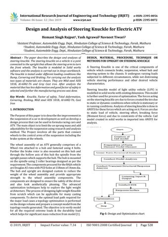
Fig-1: Design and Optimization chart
ISO 9001:2008 Certified Journal
|
Page 528