International Research Journal of Engineering and Technology (IRJET)
e-ISSN: 2395-0056
Volume: 06 Issue: 01 | Jan 2019
p-ISSN: 2395-0072
www.irjet.net
Dynamic Voltage Restorer for Compensation of Voltage Sag Mr. Rajesh Fale1, Prof. U. B. Vaidya2, Mr. P. D. Kamdi3 1Student
Scholar IEI Kolkata Guide IEI Kolkata 3Prof. DMIETR Wardha ---------------------------------------------------------------------***---------------------------------------------------------------------2Project
Abstract - Superiority of the output power delivered from
the utilities has become a major concern of the modern industries for the last decade. The rise of voltage-sensitive load equipment has made industrial processes much more vulnerable to deprivation in the quality of power supply. Voltage variations, often in the form of voltage sags and swells, can cause rigorous process disturbances and result in significant financial loss. The custom power devices which uses the power electronic devices, is one of the method by which power quality problems might be compensate. Among the numerous norm power devices, the dynamic voltage restorer (DVR) for use in distribution systems is a recent innovation. The mitigation capability of a DVR depends initially on the maximum voltage injection ability and within the restorer the amount of stored energy existing. In this paper a presage compensation control scheme is used to increase the voltage renovation property of the device. Using this novel method it can be shown that the disturbances occurred in the system can be corrected with less amount of storage energy. Modelling of proposed method is implemented in MATLAB SOFTWARE.
Injection Transformer
3 phase fault Vs
Control System
Voltage source Inverter
Filter
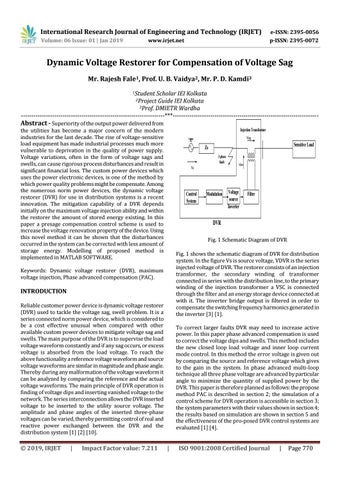
Fig. 1 Schematic Diagram of DVR Fig. 1 shows the schematic diagram of DVR for distribution system. In the figure Vs is source voltage, VDVR is the series injected voltage of DVR. The restorer consists of an injection transformer, the secondary winding of transformer connected in series with the distribution line, to the primary winding of the injection transformer a VSC is connected through the filter and an energy storage device connected at with it. The inverter bridge output is filtered in order to compensate the switching frequency harmonics generated in the inverter [3] [1].
Reliable customer power device is dynamic voltage restorer (DVR) used to tackle the voltage sag, swell problem. It is a series connected norm power device, which is considered to be a cost effective unusual when compared with other available custom power devices to mitigate voltage sag and swells. The main purpose of the DVR is to supervise the load voltage waveform constantly and if any sag occurs, or excess voltage is absorbed from the load voltage. To reach the above functionality a reference voltage waveform and source voltage waveforms are similar in magnitude and phase angle. Thereby during any malformation of the voltage waveform it can be analyzed by comparing the reference and the actual voltage waveforms. The main principle of DVR operation is finding of voltage dips and inserting vanished voltage to the network. The series interconnection allows the DVR inserted voltage to be inserted to the utility source voltage. The amplitude and phase angles of the inserted three-phase voltages can be varied, thereby permitting control of real and reactive power exchanged between the DVR and the distribution system [1] [2] [10].
Impact Factor value: 7.211
Modulation
Vdvr
DVR
INTRODUCTION
|
Sensitive Load
Zs
Keywords: Dynamic voltage restorer (DVR), maximum voltage injection, Phase advanced compensation (PAC).
Š 2019, IRJET
Vinj
3 phase AC
To correct larger faults DVR may need to increase active power. In this paper phase advanced compensation is used to correct the voltage dips and swells. This method includes the new closed loop load voltage and inner loop current mode control. In this method the error voltage is given out by comparing the source and reference voltage which gives to the gain in the system. In phase advanced multi-loop technique all three phase voltage are advanced by particular angle to minimize the quantity of supplied power by the DVR. This paper is therefore planned as follows: the propose method PAC is described in section 2; the simulation of a control scheme for DVR operation is accessible in section 3; the system parameters with their values shown in section 4; the results based on simulation are shown in section 5 and the effectiveness of the pro-posed DVR control systems are evaluated [1] [4].
|
ISO 9001:2008 Certified Journal
|
Page 770