International Research Journal of Engineering and Technology (IRJET)
e-ISSN: 2395-0056
Volume: 05 Issue: 09 | Sep 2018
p-ISSN: 2395-0072
www.irjet.net
CIRCULARLY POLARIZED C-SHAPED SLOT PATCH ANTENNA WITH RECONFIGURABLE POLARIZATION Ameelia Roseline Arulandhusamy 1, Deepa Mayilvavahanan2 1Professor,Dept.
of Electronics and Communication Engineering, Panimalar Engineering College,Tamilnadu, India 2Student, Dept. of Electronics and Communication Engineering, Panimalar Engineering College,Tamilnadu , India -------------------------------------------------------------------------***------------------------------------------------------------------------
Abstract: - A polarization reconfigurable, compact-sized, lowprofile circularly polarized, omnidirectional antenna has been designed. The circular polarization has been obtained by the combination of vertical polarization by micro-strip patch along with C-Shaped slot and horizontal polarization by bended slots etched on the ground plane. Reconfigurability of the polarization has been achieved by electronically controlling the states of the pin diodes. This changes the effective orientation of the annular slots on ground plane and Polarization can be altered between Left-Hand Circular Polarization (LHCP) and Right-Hand Circular Polarization (RHCP). The proposed design has a compact size and operates at TM01 mode. Experimental results have shown good agreement with the simulation results. This antenna has axial ratio below 3dB, gain of 5.91 dBi and return loss of -32 dB at 2.4 GHz. It is suitable for ISM band application (IEEE 802.11 b/g/n- wifi). Key Words: Compact size, Patch antenna, polarization reconfigurable , PIN diodes . 1. INTRODUCTION
Reconfigurable antenna is an emerging area of research as it helps in increasing the system capacity and realizing multiple functions. Within the extensive ambit of wireless communications, circularly polarized antennas can offer many edge over linearly polarized antennas. Circularly polarized antenna is used in wireless communication as it does not require strict alignment between the transmitting and the receiving antennas. Omni directional antenna realized by Dielectric Resonator Antenna (DRA) with alford loop [1] and monopolar patch antenna with curved branches [2] lead to high return loss but have very less gain. Patch antenna with slots and shorting vias [3] and microstrip array antennas [4] also suffer the same limitation and they have large thickness which is not suitable for the application in mobile terminals. Zeroth-order resonance patch antenna [5] has negative gain which is not desirable. Both Ring and Ushaped slot antenna [6,7] and E-shaped patch antenna [8] have less directivity. By tuning the curvatures of the vortex slots, the polarizations can be made equal in amplitude and a good CP (Circular Polarization) property is obtained [9]. Short dipole and a small loop excited by the same current are orthogonal to each other and 90 different in phase and the Omni directional CP radiation is achieved [10,11]. Antenna consists of loop elements [12], monopole elements [13] or dielectric elements [14] to provide omni directional circular polarization. A top-loaded monopole mode is excited by a Š 2018, IRJET
|
Impact Factor value: 7.211
|
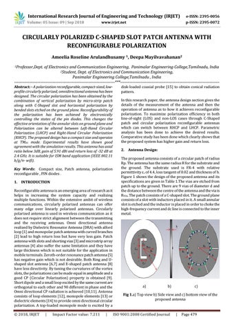
disk-loaded coaxial probe [15] to obtain conical radiation pattern. In this research paper, the antenna design section gives the details of the measurement of the antenna and then the operation of antenna as to how it achieves reconfigurable polarization. To maximize polarization efficiency in both line-of-sight (LOS) and non-LOS cases through C-Shaped patch and circular polarization reconfigurable antennas which can switch between RHCP and LHCP. Parametric analysis has been done to achieve the desired results. Comparative study has been done which clearly shows that the proposed system has higher gain and return loss. 2. Antenna Design: The proposed antenna consists of a circular patch of radius Rp. The antenna has the same radius R for the substrate and the ground. The substrate used is FR-4 with relative permittivity Îľr of 4.4, loss tangent of 0.02 and thickness of h. Figure 1 shows the design of the proposed antenna and its specifications are given in Table 1.The vias are etched from patch up to the ground. There are 9 vias of diameter d and the distance between the centre of the antenna and the via is RVIA. The patch consists of a C-shaped slot. The ground plane consists of a slot with inductors placed in it. A small annular slot is etched and the inductor is placed in order to choke the high-frequency current and dc line is connected to the inner metal.
a)
b)
c)
Fig 1.a) Top view b) Side view and c) bottom view of the proposed antenna
ISO 9001:2008 Certified Journal
|
Page 479