International Research Journal of Engineering and Technology (IRJET)
e-ISSN: 2395-0056
Volume: 05 Issue: 09 | Sep 2018
p-ISSN: 2395-0072
www.irjet.net
MODELING AND FINITE ELEMENT ANALYSIS OF DELAMINATED COMPOSITE BEAMS GALLA LAKSHMINAGARAJU 1, Dr. B VENKATA SIVA 2 1Post
Graduate, M.Tech (Machine Design), Dept. of Mechanical Engineering, Narasaraopeta Engineering College, Narasaraopeta, Andhra Pradesh, India 2 Professor, Dept. of Mechanical Engineering, Narasaraopeta Engineering College, Narasaraopeta, Andhra Pradesh, India ---------------------------------------------------------------------***--------------------------------------------------------------------Abstract - An aircraft wing is mainly subjected to lift, fuel, engine, and landing gear, inertial, structural, non-structural and other aerodynamic loads. The main load-bearing members in the wing are called spars. The spars are the principle structural members. Spars are strong beams which run span wise in the wing and carry the force and moments due to the span wise lift distribution. Wings of aircraft are attached at the root to the fuselage. A wing has two beams. One beam is usually located near the front of the wing, and the other about two-thirds of the distance toward the wing’s trailing edge beams run parallel to the lateral axis of the aircraft, from the fuselage toward the tip of the wing, and are usually attached to the fuselage by wing fittings, plain beams, or a truss. Wings of aircraft are subject to be cantilever beams with different cross sections based on requirement of aircraft. In this paper the aircraft spar wing beam with different delamination positions (X-0, X-0.3, X-0.5 & X-0.7) designed in CREO parametric software and analyzed in ANSYS software. Static structural, Fatigue and Modal analysis are performed on Rectangular cantilever composite beam with single-edge deformation. Static structural, Fatigue and Modal analysis are performed to analyze the stress, safety factor and natural frequency of different materials at different delamination length ratios. Presently used materials are conventional materials (Aluminium alloy) but in this project we replaced with composite materials (Carbon fibre reinforced polymer, S2 glass fibre reinforced polymer & Kevlar fibre reinforced polymer). It is obtained that composite material has given better performance compared to conventional material (Aluminium alloy). Key Words: Delaminated composite beam, Fibrereinforced epoxy polymers, Aircraft wing, CREO parametric software, ANSYS, Safety factor, Life, Fatigue analysis, etc.
reactions to these loads is called a bending moment. Beams are characterized by their profile (shape of cross-section), their length, and their material. Beams are traditionally descriptions of building or civil engineering structural elements, but smaller structures such as truck or automobile frames, machine frames, and other mechanical or structural systems contain beam structures that are designed and analyzed in a similar fashion.
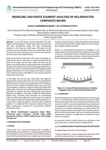
Figure 1: A statically determinate beam, bending (sagging) under a uniformly distributed load 1.1.1 OVERVIEW Historically beams were squared timbers but are also metal, stone, or combinations of wood and metal such as a flitch beam. Beams generally carry vertical gravitational forces but can also be used to carry horizontal loads (e.g., loads due to an earthquake or wind or in tension to resist rafter thrust as a tie beam or (usually) compression as a collar beam). The loads carried by a beam are transferred to columns, walls, or girders, which then transfer the force to adjacent structural compression members. In light frame construction joists may rest on beams.
1. INTRODUCTION TO BEAMS
In carpentry a beam is called a plate as in a sill plate or wall plate, beam as in a summer beam or dragon beam.
1.1 BEAM
1.1.2 CLASSIFICATION OF BEAMS BASED ON SUPPORTS
A beam (Fig. 1) is a structural element that is capable of withstanding load primarily by resisting against bending. The bending force induced into the material of the beam as a result of the external loads, own weight, span and external
In engineering, beams are of several types:
Š 2018, IRJET
|
Impact Factor value: 7.211
|
1.Simply supported - a beam supported on the ends which are free to rotate and have no moment resistance. ISO 9001:2008 Certified Journal
|
Page 273