International Research Journal of Engineering and Technology (IRJET)
e-ISSN: 2395-0056
Volume: 05 Issue: 09 | Sep 2018
p-ISSN: 2395-0072
www.irjet.net
Finite Element Method of Welding Joint in Shaft and Validation Using Different Method Anurag Mishra1,Mr. Pradeep Sahu2 1M
Tech Research Scholar SSIPMT Raipur Professor, Mechanical Engineering SSIPMT
2Assistant
-------------------------------------------------------------------***---------------------------------------------------------------Abstract:In this research work welding simulation was carries out by experimental and also on Solid work software to find out the value of stress and deflection under different loading condition. The numerical simulations show that the concentration of stress is maximum near to the joint and at the corner where the cross section has suddenly changed. In order to find out the most optimum load, the joint can bear is calculated by using experimental method in modern universal testing machine(UTM).it is very important to check & compare the solid work simulation result with the result of physical test or experiment in which the real behavior of specimen can observed. The research work deal with the physical test of specimen whose main purpose in to find out the optimum material, geometry and strength characteristics of butt weld joint. The specimen of weld joint is tested on UTM machine and corresponding output parameter as stress and deflection is monitored. The result obtained by physical experiment is validated by using different numerical approaches as Solid works simulation.
foresee the weld quality to be nourished to the robotized welding frameworks has turned out to be more basic.
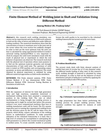
Figure 1 welding process II. Problem Identification The present study deals with finite element analysis of welded butt joint of circular bar of 13 mm diameter under the different tensile loading of alloy steel. In this research work, welding strength of material is calculated by using FEA technique. In order to find out the behavior of stress distribution and plot of deflection is verified by applying the experimental method with UTM machine.
KEYWORDS: FEA Finite element analysis, FVM- Finite Volume Method, 2 D two dimensional, FDM- Finite Difference Method, UTM- Universal Testing Machine & Simulation of solid work. I. Introduction With the expansion of interest for both high generation rates and high exactness, completely motorized or mechanized welding forms have assumed a conspicuous position in the welding field. The rate at which mechanization is being brought into welding process is surprising and it might be normal that before this present century's over more computerized machines than men in welding manufacture units will be found. The PCs assume imperative part in running the computerized welding forms and the direction given by the PC will be taken from the projects, which thusly, require calculations of the welding factors as mathematical conditions. To make powerful utilization of the robotized frameworks it is basic that a high level of certainty be accomplished in anticipating the weld parameters to achieve the coveted mechanical quality in welded joints. To create scientific models to precisely
Fig. 2 Schematic representation of welded joint An edge preparation has done before performing the welding process for proper welding process. Same boundary condition has applied for analysis of weld strength.
Fig. 3 mild steel specimen of 10 mm diameter
Š 2018, IRJET
|
Impact Factor value: 7.211
|
ISO 9001:2008 Certified Journal
|
Page 191