International Research Journal of Engineering and Technology (IRJET)
e-ISSN: 2395-0056
Volume: 05 Issue: 08 | Aug 2018
p-ISSN: 2395-0072
www.irjet.net
Finite Element Analysis of slabs, cross girders and main girders in RC T-Beam Deck Slab Bridge Manohar R1, B S Suresh Chandra2 1M
Tech, Dept. of civil Engineering , Dr. Ambedkar Institute of Technology, Bengalore, Karnataka, India. Professor, Dept. of civil Engineering , Dr. Ambedkar Institute of Technology, Bengalore, Karnataka, India. ---------------------------------------------------------------------***---------------------------------------------------------------------
2Visiting
Abstract - Tee beam deck slab bridges are the principal type among the cast-place concrete bridges, and consists of main girders, cross girders which imparts lateral rigidity to the deck slab and deck slab which runs between T-beams continuously. There are many methods have been used for the analysis of Tee beam bridge, they are classical methods such as Courbon’s method, Guyon-Massonet method, Hendry-Jaegar method for girder and pigeauds coefficient method for deck slab and Finite element method is a general method of structural analysis is approximated by the analysis of an assemblage of finite elements which are interconnected at a finite number of nodal points and represent the solution domain of the problem. The live load bending moment in a girder can be calculated by knowing the live load distribution among them. In this study the analysis of a single span two lane T-beam bridge is carried out by varying the span of 8m, 28m for analysis of girders and size of slab 3x2, 3.5x2.5, 4x3, 4.5x3.5, 5x4m by varying the spans of the bridges, deck slab depth as 200,225,250,275,300mm using software SAP 2000. In order to obtain maximum bending moment shear force and deflection, the bridge models are subjected to the IRC class AA Tracked, IRC class 70R and IRC class A loading system. The cross girders and deck slab of varying depth for different live loadings also presented in the study. It can be observed that with the increase in the span shear force, bending moment and deflection in the girder increases and also the models subjected to the IRC Class AA Tracked vehicle gives higher values of shear force, bending moment and deflection in comparison to those subjected to the IRC Class 70 R and IRC class A loadings.
cast over longitudinal girders so that the T-beam effect prevails. To impart transverse stiffness to the deck, cross girders or diaphragms are provided at regular intervals. The number of longitudinal girders depends on the width of the road. Three girders are normally provided for a two lane road bridge. T-beam bridges are composed of deck slab 20 to 25cm thick and longitudinal girders spaced from 1.9 to 2.5m and cross beams are provided at 4 to 5m interval.
Key Words: T-Beam, Finite Element Method, IRC Loadings, courbon's method.
B. Live loads
I. INTRODUCTION T-beam, used in construction, is a load bearing structure of reinforced concrete, wood, or metal, with a T shaped cross section. The top of the T-shaped cross section serves as a flange or compression member in resisting compressive stresses. The web of the beam below the compression flange serves to resist shear stress and to provide greater separation for the coupled forces of bending. A beam and slab bridge or T- beam bridge is constructed when the span is between 10 -25 m. The bridge deck essentially consists of a concrete slab monolithically Š 2018, IRJET
|
Impact Factor value: 7.211
|
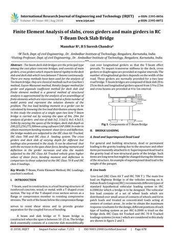
RAILINGS WEARING COAT
SHOULDER DECK SLAB CROSS GIRDER LONGITUDINAL GIRDER BEARINGS COLUMN CAP
PIERS
FOUNDATION
Fig 1: Components of T-Beam Bridge II. BRIDGE LOADING A. Dead and Superimposed Dead Load For general and building structures, dead or permanent loading is the gravity loading due to the structure and other items permanently attached to it. Superimposed dead load is the gravity load of non-structural parts of the bridge. Such items are long term but might be changed during the lifetime of the structure. An example of superimposed dead load is the weight of the parapet.
Live Load (IRC Class AA T and IRC 70R T ): The main live load on Highway Bridge is of the vehicles moving on it. Indian Roads Congress(IRC) recommends different types of standard hypothetical vehicular loading system in IRC 6:2000,for which a bridge is to be designed. The vehicular live load consists of a set of wheel loads which are distributed over small areas of contacts of wheels and form patch loads and treated as concentrated loads acting at centers of contact areas . In order to obtain the maximum response resultants for the design, different positions of each type of loading system as per IRC 6:2000 is tried on the bridge deck. IRC Class AA Tracked and IRC 70 R Tracked loadings systems (in mm ) which are considered in this study are shown in figure 2 and 3. ISO 9001:2008 Certified Journal
|
Page 678