International Research Journal of Engineering and Technology (IRJET)
e-ISSN: 2395-0056
Volume: 05 Issue: 10 | Oct 2018
p-ISSN: 2395-0072
www.irjet.net
Simulation and Analysis of Five Level SPWM Inverter ADITYA VERMA1, DONGA MAULIK M2, RUCHIT SONI3 1,2Student,
Department of Electrical Engineering, Indus Institute of Technology and Engineering, Indus University, India 3Assistant Professor at Department of Electrical Engineering, Indus Institute of Technology and Engineering Indus University, India ---------------------------------------------------------------------***---------------------------------------------------------------------------Abstract:- This project deals with the simulation of single phase multilevel inverter by sine wave pulse width modulation (SPWM) using single H bridge inverter in the Simulink MATLAB R2016a. The circuit is divided into three parts i.e., Gate Driver Circuit (control circuit), Inverter Circuit and external voltage control circuit. Inverter circuit consists of 4 IGBT connected in H bridge fashion, control circuit or gate driver circuit gets its signals by comparing carrier signal (triangular wave) and reference signal (sine wave), and the voltage control circuit consist of combination of IGBT and voltage sources which varies the collector to emitter voltage by triggering the IGBT’s with the help of pulse generators.
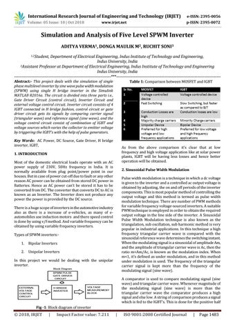
Table 1: Comparison between MOSFET and IGBT
Key Words: AC Power, DC Source, Gate Driver, H bridge inverter, IGBT,
As from the above comparison it’s clear that at low frequency and high voltage application like at solar power plants, IGBT will be having less losses and hence better operation will be obtained.
1. INTRODUCTION Most of the domestic electrical loads operate with an AC power supply of 230V, 50Hz frequency in India. It is normally available from plug point/power point in our houses. But in case of power cut-off due to fault or any other reason AC power can be obtained from stored DC power in Batteries. Hence as AC power can’t be stored it has to be converted from DC. The converter that converts DC to AC is known as an Inverter. The Inverter does not produce any power the power is provided by the DC source.
2. Sinusoidal Pulse Width Modulation Pulse width modulation is a technique in which a dc voltage is given to the inverter and a controlled ac output voltage is obtained by adjusting, the on and off periods of the inverter components. This is most popular method of controlling the output voltage and this method is termed as pulse width modulation technique. There are number of PWM methods for variable frequency voltage-sourced inverters. A suitable PWM technique is employed in order to obtain the required output voltage in the line side of the inverter. A Sinusoidal Pulse Width Modulation technique is also known as the triangulation, sub oscillation, sub harmonic method is very popular in industrial applications. In this technique a high frequency triangular carrier wave is compared with the sinusoidal reference wave determines the switching instant. When the modulating signal is a sinusoidal of amplitude Am, and the amplitude of triangular carrier wave is Ac, then the ratio m=Am/Ac, is known as the modulation index. When m<1, it’s defined as under modulation, and in this method under modulation is used. The frequency of the triangular carrier signal is kept more than the frequency of the modulating signal (sine wave).
There is a huge scope of inverters in the automotive industry also as there is a increase of e-vehicles, as many of eautomobiles use induction motors and there speed control is done by using v/f method. And variable frequency can be obtained by using variable frequency inverters. Types of SPWM inverters:1.
Bipolar Inverters
2.
Unipolar Inverters
In this project we would be dealing with the unipolar inverter.
A comparator is used to compare modulating signal (sine wave) and triangular carrier wave. Whenever magnitude of the modulating signal (sine wave) is more than the triangular carrier wave the comparator produces a high signal and else low. A string of comparison produces a signal which is fed to the IGBT’s. This is done for the positive half Fig -1: Block diagram of inverter
© 2018, IRJET
|
Impact Factor value: 7.211
|
ISO 9001:2008 Certified Journal
|
Page 1483