International Research Journal of Engineering and Technology (IRJET)
e-ISSN: 2395-0056
Volume: 04 Issue: 09 | Sep -2017
p-ISSN: 2395-0072
www.irjet.net
Free Vibration and Transient analysis of a Camshaft Assembly Using ANSYS B.Rajkumar1, S.Mahaboob Basha2 1PG
student,department of mechanical engineering,Chiranjeevi Reddy Institute of Engineering and Technology,Anantapur,AP-515001 2Assistant professor,department of mechanical engineering, Chiranjeevi Reddy Institute of Engineering and Technology,Anantapur,AP-515001 ---------------------------------------------------------------------***---------------------------------------------------------------------
Abstract: A camshaft is a rotating cylindrical shaft used to
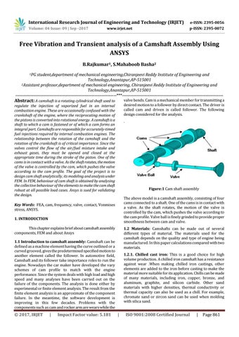
valve bends. Cam is a mechanical member for transmitting a desired motion to a follower by direct contact. The driver is called cam and driven is called follower. The following design considered for the analysis.
regulate the injection of vaporized fuel in an internal combustion engine. These are occasionally confused with the crankshaft of the engine, where the reciprocating motion of the pistons is converted into rotational energy. A camshaft is a shaft to which a cam is fastened or of which a cam forms an integral part. Camshafts are responsible for accurately-timed fuel injections required by internal combustion engines. The relationship between the rotation of the camshaft and the rotation of the crankshaft is of critical importance. Since the valves control the flow of the air/fuel mixture intake and exhaust gases, they must be opened and closed at the appropriate time during the stroke of the piston. One of the cams is in contact with a valve. As the shaft rotates, the motion of the valve is controlled by the cam, which pushes the valve according to the cam profile. The goal of the project is to design cam shaft analytically, its modeling and analysis under FEM. In FEM, behaviour of cam shaft is obtained by analysing the collective behaviour of the elements to make the cam shaft robust at all possible load cases. Ansys is sued for validating the design.
.
Figure:1 Cam shaft assembly The above model is a camshaft assembly, consisting of four cams connected to a shaft. One of the cams is in contact with a valve. As the shaft rotates, the motion of the valve is controlled by the cam, which pushes the valve according to the cam profile. Valve ball is finely grinded to provide proper smoothness between cam and valve.
Key Words: FEA, cam, frequency, valve, contact, Vonmises stress, ANSYS. 1. INTRODUCTION This chapter explains brief about camshaft assembly components, FEM and about Ansys
1.2 Materials: Camshafts can be made out of several different types of material. The materials used for the camshaft depends on the quality and type of engine being manufactured. In this paper calculations compared with two materials.
1.1 Introduction to camshaft assembly: Camshaft can be defined as a machine element having the curve outlined or a curved grooved, gives the predetermined specified motion to another element called the follower. In automotive field, Camshaft and its follower take importance roles to run the engine. Nowadays the car maker have developed the vary schemes of cam profile to match with the engine performance. Since the system deals with high load and high speed and many analyses have been carried out on the failure of the components. The analysis is done either by experimental or finite element analysis. The result from the finite element analysis is an approximate of the component failure. In the meantime, the software development is improving in this few decades. Problems with the components such as cam and rocker arm are wears while the
Š 2017, IRJET
|
Impact Factor value: 5.181
1.2.1. Chilled cast iron: This is a good choice for high volume production. A chilled iron camshaft has a resistance against wear .When making chilled iron castings, other elements are added to the iron before casting to make the material more suitable for its application. Chills can be made of many materials, including iron, copper, bronze, and aluminum, graphite, and silicon carbide. Other sand materials with higher densities, thermal conductivity or thermal capacity can also be used as a chill. For example, chromate sand or zircon sand can be used when molding with silica sand.
|
ISO 9001:2008 Certified Journal
|
Page 861