International Research Journal of Engineering and Technology (IRJET)
e-ISSN: 2395-0056
Volume: 04 Issue: 08 | Aug -2017
p-ISSN: 2395-0072
www.irjet.net
Design and Analysis of Lug Joint in an Airframe Structure Using Finite Element Method C.V.Rama kishan1, A.Mahaboob Basha2 1PG
student,department of mechanical engineering,Chiranjeevi Reddy Institute of Engineering and Technology,Anantapur,AP-515001 2Assistant professor,department of mechanical engineering, Chiranjeevi Reddy Institute of Engineering and Technology,Anantapur,AP-515001 ---------------------------------------------------------------------***---------------------------------------------------------------------
Abstract - Lugs are joint type elements most widely used as
structural supports for pin connections type assemblies. Lug and pin joints have been designed based on theoretical strength of materials models and experimental data developed in the 1950’s. With the increasing technology in mathematics usage of numerical methods like finite element analysis (FEA) code components can be tested virtually. It is important to determine whether the results obtained from Finite element analysis with the standard theoretical acceptable values. This project deals with the design and analysis of a typical lug joint representative of an airframe structure applications. The design will provide safety against a) Lug failure, b) Pin failure. The types of loadings to be considered here is axial load. Aircraft design practices will be used for calculations. Simplified geometry was modeled in ANSYS Software. Margin of safety for each lug joint component was calculated using two methods, max peak stress and stress averaged over the contact area. Using peak stress was very conservative and predicted margins were much less than those calculated from the theoretical calculations. Key Words: FEA, lugs, pin, margin of safety, Vonmises stress, ANSYS. 1. INTRODUCTION Lugs are connector type elements used as structural supports for pin connections. A lug, also known as a lifting lug is essentially a plate with a hole in it where the hole is sized to fit a clevis pin. Lugs are used in combination with clevis pins to transmit load between different mechanical components. In olden days prior to the 1950’s, lugs were overdesigned as weight, cost and space were not design driving factors for joints. With the reducing of weight, cost, feasibility, availability and space requirements in the aerospace industry, a more accurate precise method of lug analysis was required. Analysis of a lug is deceptively complex since there are several simultaneous, interacting failure modes. These failure modes are associated with different areas of the lug Typical position of lug joint in aero structure is shown in figure 1
© 2017, IRJET
|
Impact Factor value: 5.181
|
Figure:1 Vertical Tail to Fuselage Attachment Points and Associated Lug Geometry
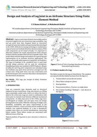
1.1 Failure modes of a Lug The failure modes for the lug are listed below. The numbers correspond with the labeled sections from the figure 2: 1.
Tension failure across the net section
2.
Shear failure along two planes
3.
Bearing failure
4.
Hoop tension failure / fracture on single plane
5.
Out of plane buckling ("dishing") -- (not shown in the figure)
Figure:2 Failure modes
ISO 9001:2008 Certified Journal
| Page 2282