International Research Journal of Engineering and Technology (IRJET)
e-ISSN: 2395-0056
Volume: 04 Issue: 08 | Aug -2017
p-ISSN: 2395-0072
www.irjet.net
Design and Simulation of Two Way Power Divider in S Band Renu Kumari 1, Vishal Acharya 2 1,2 MTech RKDF IST , Sarvepalli RadhaKrishnan University ,Bhopal 462026 ----------------------------------------------------------------------------------------------------------------------------------------------2. Schematic Design Abstract - In this paper Design and Simulation of Wilkinson
Power Divider is done using ADS Simulation tool . Substrate used for the design is LTCC951PT. Equal spilt 0 degree phase shift power divider is designed using Simulation tool ADS2011 Key Words: Wilkinson Power divider, LTCC951PT Microstrip line , ADS2011, S parameter, Isolation
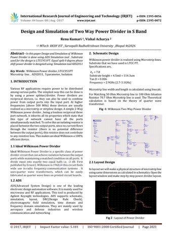
Wilkinson power divider is realized using Microstrip lines. Substrate that we have used is LTCC PT. Specifications are, = 7.8 Substrate height = 4.5mil = 114.3um Tan D = 0.006 Frequency = 2.9GHz (2.7-3.1GHz)
1. INTRODUCTION Various RF applications require power to be distributed among various paths. The simplest way this can be done is by using a power splitter/divider. Power dividers are reciprocal devices, i.e. they can also be used to combine power from output ports into the input port. At higher frequencies (above 500 MHz) these devices are usually realized as a microstrip or stripline design. A simple 2-Way Wilkinson power divider , being a lossless reciprocal three port network, it inherits all its properties which state that this type of network cannot have all the ports simultaneously matched. To solve this an isolating resistor is placed between the two output ports, since no current flows through the resistor (there is no potential difference between the output ports), this resistor does not contribute to any resistive loss. This makes an ideal Wilkinson a 100% efficient device.
Microstrip line width and length is calculated using linecalc. For Matching 50 Ohm Microstrip line to 100 Ohm Isloation Resistor 70.7 Ohm Microstrip line is used. The Theoretical calculation is based on the theory of quarter wave transformer. Fig -1: Wilkinson Two Way Power Divider
1.1 Ideal Wilkinson Power Divider Ideal Wilkinson Power Divider is a specific class of power divider circuit that can achieve isolation between the output ports while maintaining a matched condition on all ports. It divide input into exactly two equal halfs i.e. -3 dB. First published by Ernest J. Wilkinson in 1960,[1] this circuit finds wide use in radio frequency communication systems . It uses quarter wave transformers, which can be easily fabricated as quarter wave lines on printed circuit boards.
2.1 Layout Design In layout we will make a physical structure of microstrip line using same dimensions as calculated in schematics. Open the layout window and make step by step power divider layout.
1.2 ADS ADS(Advanced System Design) is one of the leading electronic design automation software. It is mainly used for microwave and RF applications. This tool is produced by Agilent Keysight technologies. ADS supports schematic, simulation, layout, DRC(Design Rule Check), electromagnetic field simulation, time domain and frequency domain simulations. They are mainly used by aerospace and defense industries and wireless communication and networking Fig 2 : Layout of Power Divider
Š 2017, IRJET
|
Impact Factor value: 5.181
|
ISO 9001:2008 Certified Journal
| Page 2021