International Research Journal of Engineering and Technology (IRJET) Volume: 04 Issue: 05 | June -2017
www.irjet.net
e-ISSN: 2395 -0056 p-ISSN: 2395-0072
Assertion based verification strategy for a generic first in first out (FIFO) Naveen T V1, Dr. M V Latte2, Mr. Sathish Shet3, Mr. Shashidhara H R4 1 Mtech
in VLSI Design and Embedded Systems, Dept of ECE, JSSATE Bengaluru 2The Principal, JSSATE Bengaluru 3Asst Professor, Dept of ECE, JSSATE Bengaluru 4Asst Professor, Dept of ECE, JSSATE Bengaluru ---------------------------------------------------------------------***--------------------------------------------------------------------Abstract: A generic FIFO is designed using a system 2. ARCHITECTURAL VIEW OF FIFO AND ITS Verilog coding technique. The pointers will indicate the INTERFACES. status of the FIFO, the flag information’s like full, empty, almost full, almost empty will be indicated and the FIFO will have a synchronous RESET capability. The functional verification will be done using assertion technique. The verification plan affords a definition of the test bench, verification properties, test surroundings, coverage sequences, application of test cases, and verification procedures for the FIFO design. The desires of this plan isn't always only to offer an define on how the aspect will be examined, but additionally to offer a straw man file that can be scrutinized by other design and system engineers to refine the verification technique.
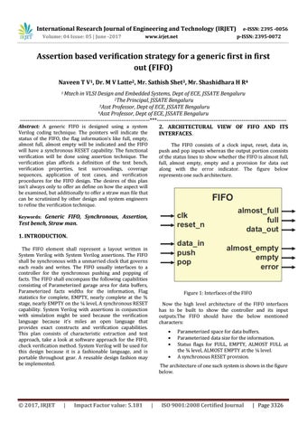
The FIFO consists of a clock input, reset, data in, push and pop inputs whereas the output portion consists of the status lines to show whether the FIFO is almost full, full, almost empty, empty and a provision for data out along with the error indicator. The figure below represents one such architecture.
Generic FIFO, Synchronous, Assertion, Test bench, Straw man. Keywords:
1. INTRODUCTION. The FIFO element shall represent a layout written in System Verilog with System Verilog assertions. The FIFO shall be synchronous with a unmarried clock that governs each reads and writes. The FIFO usually interfaces to a controller for the synchronous pushing and popping of facts. The FIFO shall encompass the following capabilities consisting of Parameterized garage area for data buffers, Parameterized facts widths for the information, Flag statistics for complete, EMPTY, nearly complete at the ¾ stage, nearly EMPTY on the ¼ level, A synchronous RESET capability. System Verilog with assertions in conjunction with simulation might be used because the verification language because it's miles an open language that provides exact constructs and verification capabilities. This plan consists of characteristic extraction and test approach, take a look at software approach for the FIFO, check verification method. System Verilog will be used for this design because it is a fashionable language, and is portable throughout gear. A reusable design fashion may be implemented.
© 2017, IRJET
|
Impact Factor value: 5.181
Figure 1: Interfaces of the FIFO Now the high level architecture of the FIFO interfaces has to be built to show the controller and its input outputs.The FIFO should have the below mentioned characters:
Parameterized space for data buffers. Parameterized data size for the information. Status flags for FULL, EMPTY, ALMOST FULL at the ¾ level, ALMOST EMPTY at the ¼ level. A synchronous RESET provision.
The architecture of one such system is shown in the figure below.
|
ISO 9001:2008 Certified Journal
| Page 3326