International Research Journal of Engineering and Technology (IRJET)
e-ISSN: 2395 -0056
Volume: 04 Issue: 06 | June -2017
p-ISSN: 2395-0072
www.irjet.net
Mathematical Modelling and Simulation of Compensator for Dynamical System Saroja Chavan1, Prof. A. B. Patil 2 1PG
Scholar, Pimpri Chinchwad College of Engg., Pune Professor Pimpri Chinchwad College of Engg., Pune ---------------------------------------------------------------------***--------------------------------------------------------------------2Assistant
Abstract - As the technology is growing the new
To ensures the stability and performance of a guided missile system we will have to develop an algorithm for lag compensator
applications are coming out which need both speed as well as position control for better and efficient performance. Brushless DC motor find a various application in control system due to its advantages over conventional DC motor. But there are different problems in work operation due to fast dynamics and instability. Therefore, in dynamical system, controller plays an important role to achieve stability and to get desired results. To meet this requirement, the response of brushless dc drive system need to be improved. The performance of the typical brushless drive system found to be sluggish. So, it is necessary to improve the performance of such system to expected level as this system find an application in most of the guided missiles with movable control surfaces or fins. To overcome the shortcomings of conventional method, this system gives compensator design used to improve steady state response and transient response of the system to accommodate required application.
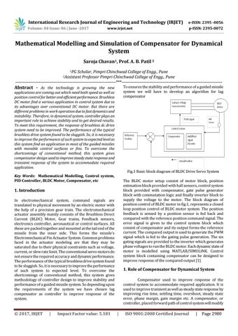
Fig.1 Basic block diagram of BLDC Drive Servo System
Key Words: Mathematical Modelling, Control system, PID Controller, BLDC Motor, Compensator, etc
The BLDC motor setup consist of motor block, position estimation block provided with hall sensors, control system block provided with compensator, gate pulse generator block with commutation logic and finally inverter block to supply the voltage to the motor. The block diagram of position control of BLDC motor in fig.1, represents a closed loop position control of BLDC motor system. The position feedback is sensed by a position sensor is fed back and compared with the reference position command signal. The error signal is given to the control system block which consist of compensator and its output forms the reference current. The compared output is used to generate the PWM signal which is fed to the gating pulse generation. The six gating signals are provided to the inverter which generates phase voltages to run the BLDC motor. Each dynamic state of motor is modelled using MATLAB/SIMULINK. Control system block containing compensator can be designed to improve response of the compared output [1].
1. Introduction In electromechanical system, command signals are translated to physical movement by an electric motor with the help of a precision gear train. The electromechanical actuator assembly mainly consists of the Brushless Direct Current (BLDC) Motor, Gear trains, Feedback sensors, electronics controller, aeronautical or control surfaces. All these are packed together and mounted at the tail end of the missile from the inner side. This forms the missile’s Electromechanical Fin Actuator System. Common problems faced in the actuator modeling are that they may be saturated due to their physical constraints such as voltage, current, or slew rate limit. The conventional servo motors do not ensure the required accuracy and dynamic performance. The performance of the typical brushless drive system found to be sluggish. So, it is necessary to improve the performance of such system to expected level. To overcome the shortcomings of conventional method, this system gives methodology of controller design to improve stability and performance of a guided missile system. So depending upon the requirements of the system we have chosen lag compensator as controller to improve response of the system.
Š 2017, IRJET
|
Impact Factor value: 5.181
1. Role of Compensator for Dynamical System Compensator used to improve response of the control system to accommodate required application. It is used to improve transient as well as steady state response by improving rise time, settling time, overshoot, steady state error, phase margin, gain margin etc. A compensator, or controller, placed forward path of control system will modify
|
ISO 9001:2008 Certified Journal
|
Page 2980