International Research Journal of Engineering and Technology (IRJET)
e-ISSN: 2395 -0056
Volume: 04 Issue: 01 | Jan -2017
p-ISSN: 2395-0072
www.irjet.net
Printed L-Slot Antenna For Wireless Application Prof.Y.S.Santawani1, Prof.A.R.Bari2, Prof.S.K.Khode3, Prof.C.R.Kuwar4 1,2,3Assistant
Professor,Dept.of Electronics & Telecommunication,SSBT’s COET,Bambhori,Jalgaon,M.S,INDIA Professor,Dept.of Electronics & Telecommunication,Zeal COE&R,Pune,M.S,INDIA ---------------------------------------------------------------------***--------------------------------------------------------------------4Assistant
Abstract - The intend of this paper is to design a antenna
which isutilized for wireless application.. Two unequal L slots are introduced at the left edge of the patch to reduce the resonant frequency. The antenna resonant at three different frequencies are obtained at 3.58 GHz, 5.16 GHz and 6.13 Ghz with return loss of 11.50 dB, 14.23 dB and 13.40 respectively. The characteristics of the designed structure are investigated by using MoM based electromagnetic solver, IE3D. An extensive analysis of the return loss, VSWR, gain and Directivity of the proposed antenna is presented. The simple configuration and low profile nature of the proposed antenna leads to easy fabrication and make it suitable for the applications in Wireless communication system. Mainly it is developed to operate in the Wi-Fi, Wi-MAX & WLAN application. Key Words: SLOT, IE3D, RETURN LOSS, VSWR
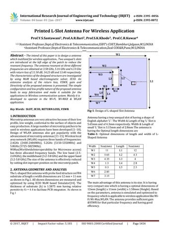
Fig-1: Design of L-shaped Slot Antenna
1.INTRODUCTION Microstrip antennas are very attractive because of their low profile, low weight, conformal to the surface of objects and easy production. A large number of microstrip patches to be used in wireless applications have been developed [1–10]. Design of WLAN antennas also got popularity with the advancement of microstrip antennas [11-15]. Wireless local area network (WLAN) requires three bands of frequencies: 2.4GHz (2400-2484MHz), 5.2GHz (5150-5350MHz) and 5.8GHz (5725-5825MHz). WiMax(WorldwideInteroperability for Microwave access) has three allocated frequency bands. The low band (2.52.69GHz), the middleband (3.2-3.8 GHz) and the upper band (5.2-5.8 GHz).The size of the antenna is effectively reduced by cutting slot inproper position on the microstrip patch.
2. ANTENNA GEOMETRY AND ANALYSIS The L-shaped Slot antenna with probe feed structure on FR4 substrate of length x width dimensions are 12 mm × 11 mm as shown in Fig.1. All shown dimensions are measured and optimized by using IE3D MoM based Simulator[14]. The thickness of substrate (h) is 1.5875 mm having relative permittivity €r = 4.4 to facilitate PCB integration. As shown in Fig.1
© 2017, IRJET
|
Impact Factor value: 5.181
|
Antenna having a twp unequal slot of having a shape of English alphabet ‘L”. The Width & Length of big ‘L’ Slot is 5.65mm and of 4.3mm respectively. Width & Length of small ‘L’ Slot is 3.15mm and of 2.8mm The antenna is having the Optimal length dimensions are Table-1: Optimal dimensions of length and width of LShaped Antenna Width W1
Size(mm) 11
Length L1
W2 W3 W4 W5
5.65 4.35 1.3 0.3
L2 L3 L4 L5
W6 W7
2.85 3.15
Size(mm) 12 4.3 4 2.8 2.5
The main advantage of this antenna is its size. It is having very compact size which is having a optimal dimensions of 12mm (length) x 11mm (width) x 1.58mm (Height). Based on the parameters, antenna is simulated and optimized to frequency which is applicable to wireless application like WiFi Wi-Max,WLAN. The antenna provides sufficient gain &VSWR for that particular frequency and having good efficiency.
ISO 9001:2008 Certified Journal
|
Page 1454