International Research Journal of Engineering and Technology (IRJET)
e-ISSN: 2395 -0056
Volume: 04 Issue: 01 | Jan -2017
p-ISSN: 2395-0072
www.irjet.net
Simulation of H6 full bridge Inverter for grid connected PV system using SPWM technique K. Raghava Reddy 1, M. Mahesh 2, M. Vijaya Kumar 3 1Student, 2AdHoc
Dept. of Electrical & Electronics Engineering, JNTUA, Anantapuram, A.P., India
lecturer, Dept. of Electrical & Electronics Engineering, JNTUA, Anantapuram, A.P., India
3Professor,
Dept. of Electrical & Electronics Engineering, JNTUA, Anantapuram, A.P., India
---------------------------------------------------------------------***---------------------------------------------------------------------
Abstract - Transformer less inverter is widely used in grid-
systems could feed into the public utility grid without galvanic isolation between the DC and AC circuits that could allow the passage of dangerous DC faults to be transmitted to the AC side. However, since 2005, the NFPA's NEC allows transformer less (or non-galvanically) inverters by removing the requirement that all solar electric systems be negative grounded and specifying new safety requirements. From the safety point of view, most of the PV grid-tied inverters employ line-frequency transformers to provide galvanic isolation in commercial structures in the past. However, linefrequency transformers are large and heavy, making the
tied photovoltaic (PV) generation systems, due to the benefits of achieving high efficiency and low cost. Various transformer less inverter topologies have been proposed to meet the safety requirement of reducing leakage currents. In the proposed paper, a family of transformer less H6 inverter topologies with low leakage currents is proposed, and the intrinsic relationship between H5 Inverter topology, highly efficient and reliable inverter concept (HERIC) topology, and the proposed H6 Inverter topology has been discussed well. One of the proposed H6 inverter topologies is taken as an example for detail analysis with operation modes and modulation strategy. The proposed H6 Inverter topologies have the following advantages and evaluated by simulation results: The conversion efficiency of the novel H6 Inverter topology is better than that of the H5 Inverter topology, and its thermal stress distribution is better than that of the H5 Inverter topology. The leakage current is almost the same as HERIC Inverter topology, and meets the safety standard. The excellent DM performance is achieved like the isolated full-bridge inverter with unipolar SPWM. Therefore, the proposed H6 Inverter topologies are good solutions for the single-phase transformer less PV grid-tied inverters.
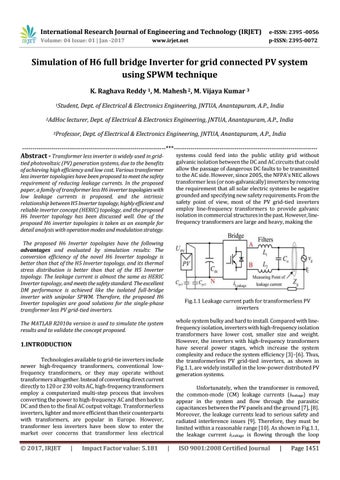
Fig.1.1 Leakage current path for transformerless PV inverters whole system bulky and hard to install. Compared with linefrequency isolation, inverters with high-frequency isolation transformers have lower cost, smaller size and weight. However, the inverters with high-frequency transformers have several power stages, which increase the system complexity and reduce the system efficiency [3]–[6]. Thus, the transformerless PV grid-tied inverters, as shown in Fig.1.1, are widely installed in the low-power distributed PV generation systems.
The MATLAB R2010a version is used to simulate the system results and to validate the concept proposed.
1.INTRODUCTION Technologies available to grid-tie inverters include newer high-frequency transformers, conventional lowfrequency transformers, or they may operate without transformers altogether. Instead of converting direct current directly to 120 or 230 volts AC, high-frequency transformers employ a computerized multi-step process that involves converting the power to high-frequency AC and then back to DC and then to the final AC output voltage. Transformerless inverters, lighter and more efficient than their counterparts with transformers, are popular in Europe. However, transformer less inverters have been slow to enter the market over concerns that transformer less electrical
Š 2017, IRJET
|
Impact Factor value: 5.181
Unfortunately, when the transformer is removed, the common-mode (CM) leakage currents (ileakage) may appear in the system and flow through the parasitic capacitances between the PV panels and the ground [7], [8]. Moreover, the leakage currents lead to serious safety and radiated interference issues [9]. Therefore, they must be limited within a reasonable range [10]. As shown in Fig.1.1, the leakage current iLeakage is flowing through the loop
|
ISO 9001:2008 Certified Journal
|
Page 1451