International Research Journal of Engineering and Technology (IRJET) Volume: 03 Issue: 09 | Sep-2016
www.irjet.net
e-ISSN: 2395 -0056 p-ISSN: 2395-0072
THE FORGE STEEL CRANKSHAFT ANALYSIS USING FINITE ELEMENT METHOD Prashant.A.Patil1, Mahesh Kamkar2, Dr.Ashok.M.Hulagabali3, Dr.J.Shivakumar4 1M.Tech
Student(Machine Design),Maratha Mandal Engineering College, Belagavi, Karnataka, India Prof., Mechanical Dept., Maratha Mandal Engineering College, Belagavi, Karnataka, India 3Asst. Prof., Mechanical Dept., Maratha Mandal Engineering College, Belagavi, Karnataka, India 4Principal, Chattisgarh Engineering College,Durg, Chattisgarh, India ---------------------------------------------------------------------***--------------------------------------------------------------------2Asst.
Abstract - The primary aim of the present work is to
The connecting rods also have bearings inserted between the crankshaft and the connecting rods. The bearing material will be a soft alloy of metals that provides a replaceable wear surface and prevents galling between two similar metals (i.e., crankshaft and connecting rod). Each bearing is split into halves to alloy assembly of the engine. There are many sources of failure in the vehicle crankshaft. They could be categorized as operating sources (Ex-High operating oil temperature, Oil Absence), mechanical sources(Ex-Misalignments of the crankshaft on assembly, Crankshaft vibrations) and repairing sources(ExHigh surface roughness(due to improper grinding, originating wearing), Misalignment of the crankshaft (due to improper alignment of the crankshaft)). Henry et al. [1] performed the experiment on crankshaft durability assessment program based on three dimensional mechanical analyses was developed by RENAULT®. It used to predict the durability and calculate the fatigue performance of crankshafts. Prakash et al. [2] studied a complete crankshaft model using the solid elements of ANSYS software. Aksoy et al. [3] performed study of single cylinder diesel engines which are extensively used in agricultural areas for several purposes such as water pumping. Borges et al. [4] performed the push investigation to assess the general auxiliary effectiveness of the wrench, worried with the homogeneity and greatness of anxieties and also the sum and confinement of anxiety fixation focuses of engine. Chien et al. [5] studied the impact of the leftover anxiety prompted by the filet moving procedure on the exhaustion procedure of a pliable cast iron crankshaft. Simon et al. [6] studied crankshaft which is often designed with a small fillet radius. The crankshaft fillet rolling process is one of the commonly adopted methods in engineering to improve fatigue life of the crankshaft. Combustion and inertia forces acting on the crankshaft cause two types of loading on the crankshaft structure, bending load and torsional load. For this failure there is need to FEA analysis of this crankshaft to reduce the stress on critical area. For the stress analysis of crankshaft, a forged micro alloy steel crankshaft is chosen as shown in
analyze Finite Element Analysis (FEA) of the forge steel crankshaft. In this present exploration analysis is carried on fashioned Micro Alloy Steel crankshaft. This crankshaft is utilized as a part of new TATA Safari 2.2 L DICOR ® vehicle, which has a place with in line four chamber crankshaft of four stroke diesel motor. The Bharat Forge Industry is manufacturer of this crankshaft. Yet, crankshaft is fizzled for different reasons. Thusly there is requirement for examination of the crankshaft to discover the reason of its inappropriate functioning in bending stress, utilizing the FEA investigation. In this study a static investigation is led on this crankshaft, with single crankpin of crankshaft. Cross examine is done utilizing the ANSYS programming. The element type used for crankshaft is solid 3D and tetra element. Loading and boundary condition depend upon the actual position of parts in working condition. And other analysis inputs are taken from the engine specification chart.
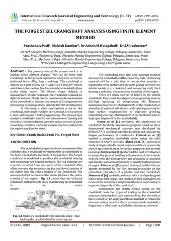
Key Words: Crank Shaft, Crank Pin, Forged Steel 1.INTRODUCTION The crankshaft changes the direct movement of the cylinders into a rotational movement that is transmitted to the heap. Crankshafts are made of forged steel. The forged crankshaft is machined to produce the crankshaft bearing and connecting rod bearing surfaces. The rod bearings are eccentric or offset from the centre of the crankshaft .This offset converts the reciprocating (up and down) motion of the piston into the rotary motion of the crankshaft. The amount of offset determines the stroke (distance the piston travels) of the engine. Fig. 1.1 shows that the ordinary crankshaft with principle diary that backing the crankshaft in the motor square.
Fig. 1.1 Ordinary crankshaft with principle diary that backing the crankshaft in the motor square
© 2016, IRJET
|
Impact Factor value: 4.45
|
ISO 9001:2008 Certified Journal
|
Page 1008