International Research Journal of Engineering and Technology (IRJET)
e-ISSN: 2395 -0056
Volume: 03 Issue: 08 | Aug-2016
p-ISSN: 2395-0072
www.irjet.net
Design and implementation of increasing efficiency of solar power by using MOSFET L-C dc-dc converter Vijoy Kumar Peddiny, Ravi.U.Magre, Amit.M.Paikrao, Nikita.A.Sonkamle PES College of Engineering, Aurangabad Assistant Professor, Dept. of Electrical Engineering, Aurangabad, Maharashtra, India ---------------------------------------------------------------------***---------------------------------------------------------------------
Abstract – In this method, we are needed to improve the
efficiency level of solar power using mosfet switching. Mostly using dc-dc converters, such as chopper, DC chopper is a fixed dc input voltage to variable dc output voltage. The regulator is used for increasing and decreasing of voltage given to battery parts. There are various types of dc-dc converters like boost and buck converters respectively. Solar power depends on the light intensity of day and night effect. We need to be a secure optimal charging given to battery for the running purpose It shows the matching of output voltages and currents. With increasing demand of power utilization and power sector, we need to save energy by using this technology. We are showing you by the simulation for the input side given to the dc sources and output side required a battery charging. Key Words: Solar power, dc-dc converter, proposed topology of MOSFET,pwm, MOSFET LC switching
1. INTRODUCTION
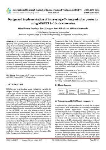
1.1 Block diagram
DC Chopper is a fixed dc input voltage to variable dc output voltage. The switches are generally passive or
Active type. Passive switches consists of a diode, where as the active switches are like MOSFET transistor. MOSFET transistors are an efficient and fast way to allow a pulse width modulation (PWM) signal to control the frequency and duty cycle of the ON and OFF time of the “switch”. More power is transferred from input to Output when Duty cycle is high. One of the advantages of the PWM is that the signal remains digital from the source i.e. from the Microcontroller to the MOSFETʼs so that any analog-to-digital signals conversion is no more needed. There are many DC-to-DC converters so far studied .Some are like Buck, Boost, BuckBoost, and Cuk. These regulators do not produce power. In fact some of the input power according to their efficiency is consumed by these Regulators. Therefore considering ideal case to maintain the same power level the adjusted voltage level affects the current level. Since current and voltage are both directly proportional to power therefore in buck mode the voltage is reduced as the current increases. While in boost mode the voltage is increased as the current decreases. The Solar Charge controller consists of various
© 2016, IRJET
| Impact Factor value: 4.45
Components like Dc-Dc Converter, Microcontroller, LCD, Temperature sensors, Voltage sensors, Current sensors, Irradiance Sensors. The Dc- Dc Converter is one among the major component of the controller which receives the input voltage from the PV panel and converts the voltage without use of transformer and gives the desired output as that required for various charging stages of Battery. The power control scheme uses semiconductor devices such as MOSFET, IGBT, etc. with various switching techniques. The designers are forced to optimization of the performance of solar power DC motor drives. These drives have now dominated the area of variable speed because of their low cost reliability and simple control the various converter topologies are a. Rectifier – Conversion of AC to DC b. Cycloconverter – Providing variable AC, Conversion of AC to AC c. Inverter – Conversion of DC to AC d. Chopper – Conversion of DC to DC i.e. Providing variable DC.Application used to saving energy.
|
Solar energy
Dc input source
Dc-dc converter
Load
1.2 Comparison of DC-DC boost converters Transformerless solutions:- In order to satisfy the stringent requirements with performance in renewable energy grid connected power applications, many researchers concentrate on how to realize high voltage gain step-up, low cost and high efficiency single-stage converters . The brief comparison of available single-stage transformer less converters will be presented below. They provide the voltage gain up to 20 using coupled inductors or switched capacitor technique. Usually the efficiencies of high voltage gain step-up converters are at the levels over 90% at sub kilowatt or single kilowatt powers. To increase the overall efficiency of converter soft switching technique as well as active clamped circuit introduction may be considered. Boost converter. The single phase single switch boost converter is a basic step-up topology (Fig. 1). The voltage gain theoretically is infinite when duty cycle reaches 1. But switch ISO 9001:2008 Certified Journal
|
Page 1342