International Research Journal of Engineering and Technology (IRJET) Volume: 03 Issue: 07 | July-2016
www.irjet.net
e-ISSN: 2395 -0056 p-ISSN: 2395-0072
Analysis of power factor correction of PV-Grid interconnected system Krishna Kumar Bhargav1, Vijay Kumar Garg2 1PG
Scholar, Electrical Engineering, UIET Kurukshetra University, Haryana, INDIA professor, Electrical Engineering, Kurukshetra University, Haryana, INDIA 1bhargavbrcm@gmail.com, 2 vkgarg2015@kuk.ac.in
2Assistant
---------------------------------------------------------------------***---------------------------------------------------------------------
Abstract - This paper explain about power factor correction topology for a single phase two wire photovoltaic (PV) system. The charge controller techniques (maximum power point tracking) is also proposed here to maintain store energy of the battery set. Boost converter is served as a boost up the voltage according to my output level. The bidirectional inverter is used as a generator, to continuous power to the load. The battery system with inverter is also used to maintain the voltage level when solar system is not capable to deliver energy to the load. A parallel power factor correction (PPFC) scheme can be satisfied with the control scheme of the inverter. A power factor correction algorithm is implemented in a DSP controller with PV system. The simulation result on a 1 KW PV system show the approximately unity power factor (PF) at the utility side. Key Words: Photovoltaic System, Boost Converter, MPPT Technique, Inverter, Utility Grid.
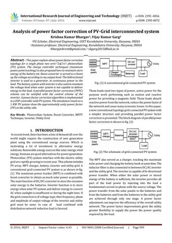
Fig. (1) A conventional grid-connected PV system Those loads need two types of power, active power for the purpose work performing such as motion and reactive power for providing a magnetic field. Those loads absorb reactive power from the network, reduce the power factor of the network and cause many economic losses. In this paper, a new conventional topology grid-connected PV system with a simpler structure and providing parallel power factor correction is presented. The block diagram of parallel power factor correction is shown in fig. (2).
1. INTRODUCTION In recent trend, there has been a lots of demand all over the world might require the construction of new generation plant using the conventional energy sources. Which is motivating a lot of investment in alternative energy solutions. Renewable energy sources like solar energy, wind energy, biomass are good alternatives for power generation. Photovoltaic (PV) system interface with the electric utility grid are rapidly growing in recent year. This scheme includes PV array, MPT charger, battery, inverter and utility grid. A conventional grid-connected PV system is as shown in fig. (1). The maximum power tracker (MPT) is combined with boost converter to obtain as much solar power as possible. The main function of DC/DC converter to store the excessive solar energy in the batteries. Inverter function is to store energy when solar PV system and deliver energy to convert AC when sunlight is insufficient or during the night time. If the grid connection is of voltage-type, then frequency, phase and amplitude of output voltage of the inverter and utility grid must be same. In case of load combined with distribution network inductive load is favored.
Š 2016, IRJET
|
Impact Factor value: 4.45
|
Fig. (2) The schematic of grid-connected PV system The MPT also served as a charger, tracking the maximum solar power and charging the battery bank at same time. The inductor filter is also connected in between DC/AC inverter and the utility grid. The inverter is capable of bi-directional power transfer. When either the solar power or stored energy of the battery is sufficient, the inverter provides all part of the load power by injecting into the load a fundamental current in-phase with the source voltage. The power transfer from the solar panels to the batteries and from the batteries and from the batteries to the utility grid are achieved through only one stage. A power factor adjustment can improve the efficiency of the overall utility network. The power factor improvement gives the utility greater flexibility to supply the power the power quality required by the load.
ISO 9001:2008 Certified Journal
|
Page 959