International Research Journal of Engineering and Technology (IRJET)
e-ISSN: 2395 -0056
Volume: 03 Issue: 02 | Feb-2016
p-ISSN: 2395-0072
www.irjet.net
Substrate Integrated Waveguide Based Leaky-Wave Antenna Sunil Dwivedi1, Prof Divyanshu Rao2, Prof Ravi Mohan3 1Sunil
Dwivedi,Mtech Student,Dept Electronics andSRIT JBP Divyanshu Rao Astt Prof,Dept of Electronics and Comm Engg,SRIT JBP 3 Prof Ravi Mohan Prof,Dept of Electronics and Comm Engg,SRIT JBP
2Prof
---------------------------------------------------------------------***---------------------------------------------------------------------
Abstract - A novel high performance, non-uniform slotted
substrate integrated waveguide leaky wave antenna has been proposed. These non-uniform slots are used to reduce the side lobes and to improve the radiation efficiency as well. The proposed structure has enhanced antenna gain and reduced reflection loss also. This leaky wave antenna also works in TE10 mode same as previous LWAs. So, three modes are propagating in the structure; leaky wave mode, proper waveguide mode and surface wave mode. The proposed nonuniform leaky wave antenna also scans efficiently from broadside to near end-fires. Key Words: Non Uniform slotted,leaky wave antenaa,side lobes,radiation Efficiency.
1.INTRODUCTION A transverse non-uniform slot antenna is shown in Figure 3.1 which is the part of the structure that clearly depicts the parameters of proposed SIW. The period of the vias (s) is of the order of operating wavelength and length of the slot L is constant, only slot width is varied in geometric progression of ratio 1.01625. The slot width is varied in the central section of 220 mm length of the geometry symmetrically as shown in Figure 3.2. The width of first slot at the left extreme of the guide is 0.30mm. The width of subsequent slots increases in geometric progression to maximum value of 0.60mm at the center (nth slot) and goes on decreasing symmetrically thereafter. The effective width of SIW is near about weff = 9.8 mm.
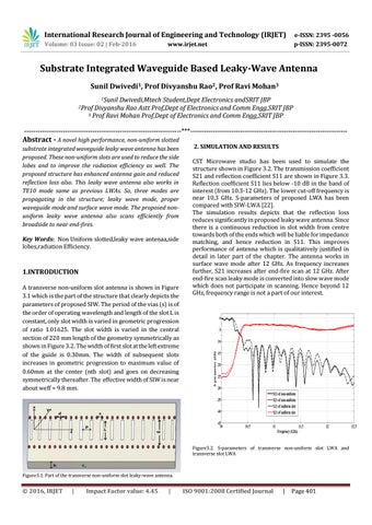
2. SIMULATION AND RESULTS CST Microwave studio has been used to simulate the structure shown in Figure 3.2. The transmission coefficient S21 and reflection coefficient S11 are shown in Figure 3.3. Reflection coefficient S11 lies below -10 dB in the band of interest (from 10.3-12 GHz). The lower cut-off frequency is near 10.3 GHz. S-parameters of proposed LWA has been compared with SIW-LWA [22]. The simulation results depicts that the reflection loss reduces significantly in proposed leaky wave antenna. Since there is a continuous reduction in slot width from centre towards both of the ends which will be liable for impedance matching, and hence reduction in S11. This improves performance of antenna which is qualitatively justified in detail in later part of the chapter. The antenna works in surface wave mode after 12 GHz. As frequency increases further, S21 increases after end-fire scan at 12 GHz. After end-fire scan leaky mode is converted into slow wave mode which does not participate in scanning. Hence beyond 12 GHz, frequency range is not a part of our interest.
Figure3.2. S-parameters of transverse non-uniform slot LWA and transverse slot LWA
Figure3.1. Part of the transverse non-uniform slot leaky-wave antenna.
Š 2016, IRJET
|
Impact Factor value: 4.45
|
ISO 9001:2008 Certified Journal
|
Page 401