International Research Journal of Engineering and Technology (IRJET)
e-ISSN: 2395 -0056
Volume: 03 Issue: 02 | Feb-2016
p-ISSN: 2395-0072
www.irjet.net
Simulation and Analysis of 5 Phase SRM Converter Diwakar Pandey Mtech Student, Dept. of Electrical Engineering, GHRCE, Maharashtra, India ---------------------------------------------------------------------***---------------------------------------------------------------------
Abstract - In this paper SRM motor modelling for five phase
10/8 switched reluctance motor (SRM) drive is presented. This paper also presents computation of Turn ON and Turn OFF angle based on linear model. A simulation running the Five phase SRM model with power converter using two IGBT’s and two diodes for each phase is performed and the parameters of the motor such as motor flux of each phase, armature current, torque and motor speed were analysed and recorded.
inductance of the excited winding is maximized. SRM is a type of synchronous machine. It has wound field coils for its stator windings and has no coils or magnets on its rotor. Both the stator and rotor have salient poles, hence, the machine is a doubly salient, singly excited machine.
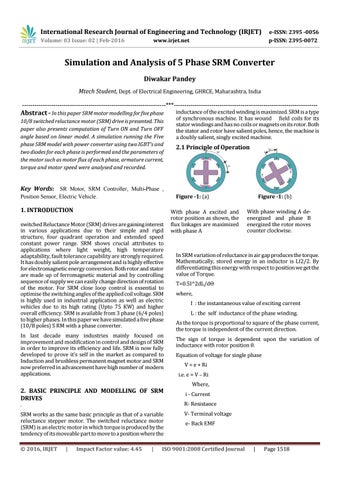
2.1 Principle of Operation
Key Words: SR Motor, SRM Controller, Multi-Phase , Figure -1: (a)
Position Sensor, Electric Vehicle.
1. INTRODUCTION switched Reluctance Motor (SRM) drives are gaining interest in various applications due to their simple and rigid structure, four quadrant operation and extended speed constant power range. SRM shows crucial attributes to applications where light weight, high temperature adaptability, fault tolerance capability are strongly required. It has doubly salient pole arrangement and is highly effective for electromagnetic energy conversion. Both rotor and stator are made up of ferromagnetic material and by controlling sequence of supply we can easily change direction of rotation of the motor. For SRM close loop control is essential to optimise the switching angles of the applied coil voltage. SRM is highly used in industrial application as well as electric vehicles due to its high rating (Upto 75 KW) and higher overall efficiency. SRM is available from 3 phase (6/4 poles) to higher phases. In this paper we have simulated a five phase (10/8 poles) S RM with a phase converter. In last decade many industries mainly focused on improvement and modification in control and design of SRM in order to improve its efficiency and life. SRM is now fully developed to prove it’s self in the market as compared to Induction and brushless permanent magnet motor and SRM now preferred in advancement have high number of modern applications.
2. BASIC PRINCIPLE AND MODELLING OF SRM DRIVES
With phase A excited and rotor position as shown, the flux linkages are maximized with phase A
T=0.5I^2dL/dƟ where, I : the instantaneous value of exciting current L : the self inductance of the phase winding. As the torque is proportional to square of the phase current, the torque is independent of the current direction. The sign of torque is dependent upon the variation of inductance with rotor position θ. Equation of voltage for single phase V = e + Ri i.e. e = V – Ri Where, i - Current R- Resistance
SRM works as the same basic principle as that of a variable reluctance stepper motor. The switched reluctance motor (SRM) is an electric motor in which torque is produced by the tendency of its moveable part to move to a position where the
V- Terminal voltage
|
Impact Factor value: 4.45
|
With phase winding A deenergized and phase B energized the rotor moves counter clockwise.
In SRM variation of reluctance in air gap produces the torque. Mathematically, stored energy in an inductor is LI2/2. By differentiating this energy with respect to position we get the value of Torque.
.
© 2016, IRJET
Figure -1: (b)
e- Back EMF
ISO 9001:2008 Certified Journal
|
Page 1518