International Research Journal of Engineering and Technology (IRJET)
e-ISSN: 2395 -0056
Volume: 03 Issue: 02 | Feb-2016
p-ISSN: 2395-0072
www.irjet.net
A simple design of broadband higher frequency microstrip patch antenna
for K band application Pushpendra Singh1, Swati Singh2 2(EC
1(EC
Department/ Amity University Rajasthan, India) Department/ CSJM University Kanpur, U.P. India)
---------------------------------------------------------------------------------------------------------------------------------------------------
Abstract-This paper presents a simple design of crossed
radiation performance. The proposed antenna design and performance presented in the next section.
taper shaped higher frequency antenna which can be used in K band. The proposed antenna design is simulated by computer simulation technology microwave studio simulator. The goal of this paper is to optimize the performance of the microstrip patch antenna at the higher frequency band. The proposed antenna geometry provides the desired bandwidth, gain and the radiation pattern. The antenna is fabricated using FR-4 substrate and parameters like return loss, VSWR, surface current distribution and input impedance are measured.
This paper is divided in 4 sections. I section presents introduction and II shows the proposed antenna design. Simulation results and discussion detail are shown in III section, while IV section presents the paper conclusion.
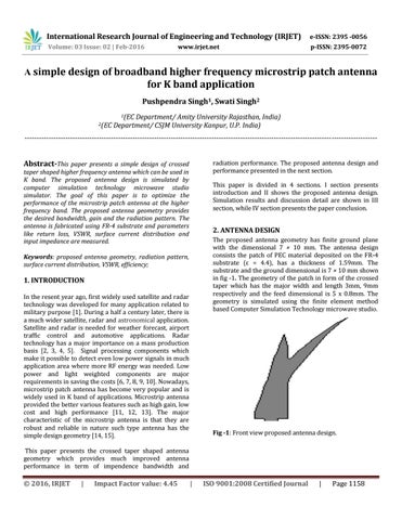
2. ANTENNA DESIGN The proposed antenna geometry has finite ground plane with the dimensional 7 × 10 mm. The antenna design consists the patch of PEC material deposited on the FR-4 substrate (ε = 4.4), has a thickness of 1.59mm. The substrate and the ground dimensional is 7 × 10 mm shown in fig -1. The geometry of the patch in form of the crossed taper which has the major width and length 3mm, 9mm respectively and the feed dimensional is 5 x 0.8mm. The geometry is simulated using the finite element method based Computer Simulation Technology microwave studio.
Keywords: proposed antenna geometry, radiation pattern, surface current distribution, VSWR, efficiency;
1. INTRODUCTION In the resent year ago, first widely used satellite and radar technology was developed for many application related to military purpose [1]. During a half a century later, there is a much wider satellite, radar and astronomical application. Satellite and radar is needed for weather forecast, airport traffic control and automotive applications. Radar technology has a major importance on a mass production basis [2, 3, 4, 5]. Signal processing components which make it possible to detect even low power signals in much application area where more RF energy was needed. Low power and light weighted components are major requirements in saving the costs [6, 7, 8, 9, 10]. Nowadays, microstrip patch antenna has become very popular and is widely used in K band of applications. Microstrip antenna provided the better various features such as high gain, low cost and high performance [11, 12, 13]. The major characteristic of the microstrip antenna is that they are robust and reliable in nature such type antenna has the simple design geometry [14, 15].
Fig -1: Front view proposed antenna design.
This paper presents the crossed taper shaped antenna geometry which provides much improved antenna performance in term of impendence bandwidth and
© 2016, IRJET
|
Impact Factor value: 4.45
|
ISO 9001:2008 Certified Journal
|
Page 1158