International Research Journal of Engineering and Technology (IRJET)
e-ISSN: 2395 -0056
Volume: 03 Issue: 01 | Jan-2016
p-ISSN: 2395-0072
www.irjet.net
Design of Compensators for Speed Control of DC Motor by using Bode Plot Techniques Abhilash D. Karmankar1, Poonam R. Hatti2, Yogita R. Ashtekar3, Dinesh L. Mute4 1, 2
B.E. 4th Year Student of Electrical Engineering Department, DMIETR, Sawangi (Meghe), Wardha (MH), India 3, 4 Asst. Prof, Electrical Engineering Department, DMIETR, Sawangi (Meghe), Wardha (MH), India
---------------------------------------------------------------------***---------------------------------------------------------------------
Abstract - This paper introduces design of different
compensators and their output response for speed control of DC motor. With this paper, engineers would be able to rapidly design compensators for speed control of DC motor. As shown by the example, the method can improve the efficiency as required. Also, with this paper we can compares the effect of different compensators on system and compare their parameters side by side. In this paper compensator is designed by using Bode Plot Techniques and MATLAB Programming, therefore it is easier to simulate any programing with the help of basic bode plot formulae and simple programming.
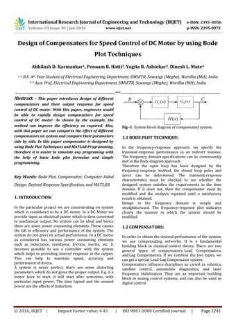
Fig -1: System block diagram of compensated system.
1.1 BODE PLOT TECHNIQUE: In the frequency-response approach, we specify the transient-response performance in an indirect manner. The frequency domain specifications can be conveniently met in the Bode diagram approach. Therefore the open loop has been designed by the frequency-response method, the closed loop poles and zeros can be determined. The transient-response characteristics must be checked to see whether the designed system satisfies the requirements in the time domain. If it does not, then the compensator must be modified and the analysis repeated until a satisfactory result is obtained. Design in the frequency domain is simple and straightforward. The frequency-response plot indicates clearly the manner in which the system should be modified.
Key Words: Bode Plot, Compensator, Computer Aided Design, Desired Response Specification, and MATLAB. 1. INTRODUCTION: In the particular project we are concentrating on system which is considered to be a DC motor. In a DC Motor we provide input as electrical power which is then converted to mechanical output. No system can be ideal and hence there are some power consuming elements. These causes the fall in efficiency and performance of the system. The system do not gives its actual performance. In a DC motor as considered has various power consuming elements such as inductance, resistance, friction, inertia, etc. It becomes possible to use a controller with the system which helps in providing desired response at the output. This can help to maintain speed, accuracy and performance of device. A system is never perfect, there are some distorting parameters which do not gives the proper output. E.g. if a motor have to start, it will start after sometime, with particular input power. The time lapsed and the unused power are the effects of distortion.
Š 2016, IRJET |
Impact Factor value: 4.45
1.2 COMPENSATORS: In order to obtain the desired performance of the system, we use compensating networks. It is a fundamental building block in classical control theory. There are two general types of compensators: Lead Compensators, and Lag Compensators. If we combine the two types, we can get a special Lead-Lag Compensator system. Compensators influence disciplines as varied as robotics, satellite control, automobile diagnostics, and laser frequency stabilization. They are an important building block in analog control systems, and can also be used in digital control.
|
ISO 9001:2008 Certified Journal
|
Page 1241