International Research Journal of Engineering and Technology (IRJET)
e-ISSN: 2395 -0056
Volume: 03 Issue: 10 | Oct -2016
p-ISSN: 2395-0072
www.irjet.net
Programmable OP-AMP Configurations Mayuresh Sardar1 1Mayuresh
Sardar: Student, Dept. of Electronics and Tele Communication Engineering, Vishwakarma Institute of Information Technology, Pune 411048, Maharashtra, India
---------------------------------------------------------------------***---------------------------------------------------------------------
Abstract - The op-amp is widely used in various modes such
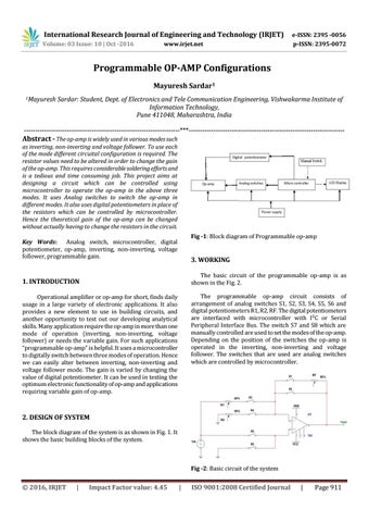
as inverting, non-inverting and voltage follower. To use each of the mode different circuital configuration is required. The resistor values need to be altered in order to change the gain of the op-amp. This requires considerable soldering efforts and is a tedious and time consuming job. This project aims at designing a circuit which can be controlled using microcontroller to operate the op-amp in the above three modes. It uses Analog switches to switch the op-amp in different modes. It also uses digital potentiometers in place of the resistors which can be controlled by microcontroller. Hence the theoretical gain of the op-amp can be changed without actually having to change the resistors in the circuit. Fig -1: Block diagram of Programmable op-amp
Key Words: Analog switch, microcontroller, digital potentiometer, op-amp, inverting, non-inverting, voltage follower, programmable gain.
3. WORKING The basic circuit of the programmable op-amp is as shown in the Fig. 2.
1. INTRODUCTION
The programmable op-amp circuit consists of arrangement of analog switches S1, S2, S3, S4, S5, S6 and digital potentiometers R1, R2, RF. The digital potentiometers are interfaced with microcontroller with I²C or Serial Peripheral Interface Bus. The switch S7 and S8 which are manually controlled are used to set the modes of the op-amp. Depending on the position of the switches the op-amp is operated in the inverting, non-inverting and voltage follower. The switches that are used are analog switches which are controlled by microcontroller.
Operational amplifier or op-amp for short, finds daily usage in a large variety of electronic applications. It also provides a new element to use in building circuits, and another opportunity to test out our developing analytical skills. Many application require the op-amp in more than one mode of operation (inverting, non-inverting, voltage follower) or needs the variable gain. For such applications “programmable op-amp” is helpful. It uses a microcontroller to digitally switch between three modes of operation. Hence we can easily alter between inverting, non-inverting and voltage follower mode. The gain is varied by changing the value of digital potentiometer. It can be used in testing the optimum electronic functionality of op-amp and applications requiring variable gain of op-amp.
2. DESIGN OF SYSTEM The block diagram of the system is as shown in Fig. 1. It shows the basic building blocks of the system.
Fig -2: Basic circuit of the system
© 2016, IRJET
|
Impact Factor value: 4.45
|
ISO 9001:2008 Certified Journal
|
Page 911