
International Research Journal of Engineering and Technology (IRJET) e-ISSN: 2395-0056
Volume: 11 Issue: 08 | Aug 2024 www.irjet.net p-ISSN: 2395-0072

International Research Journal of Engineering and Technology (IRJET) e-ISSN: 2395-0056
Volume: 11 Issue: 08 | Aug 2024 www.irjet.net p-ISSN: 2395-0072
S
G Srivani1 , Sahana R2
1Electrical and Electronics, RV College of Engineering, Bengaluru, India
2Electrical and Electronics, RV College of Engineering, Bengaluru, India ***
Abstract - Effectivetemperaturemanagementisvitalfor enhancing performance and reliability in various cooling applications. In modern cooling systems, efficient temperature regulation is essential for maintaining optimal performance and extending the lifespan of electronic components. This paper introduces a method for dynamically controlling the speed of a Brushless DC (BLDC) motor using a Proportional-Integral-Derivative (PID) controller, where the motor speed is governed by temperature variations. The control strategy is designed to increase the motor speed as the ambient temperature rises, therebyenhancingthecoolingeffect topreventoverheating. The PID controller plays a critical role in this process by continuously adjusting the Pulse Width Modulation (PWM) signals based on feedback from a temperature sensor. This ensuresthatthemotorrespondsaccuratelyandpromptly to temperature changes. By fine-tuning the PID parameters, the system achieves a balance between rapid response and minimal overshoot, reducing steady-state error and avoiding unnecessary power consumption. Experimental validation shows that this method effectively maintains the desired temperature range, even under fluctuating thermal conditions, demonstrating its suitability for applications where precise temperature control is crucial. The proposed approach not only optimizes the cooling efficiency but also enhances the overall stability and reliability of the system, making it a valuable solution for temperature-sensitive environments.
Key Words: - BLDC motor, Cooling applications, PID ControllerTemperaturecontrol
Thermal management is a critical aspect of modern electronic and mechanical systems, particularly in environments where components are sensitive to heat. In applications such as data centers, industrial automation, and consumer electronics, maintaining an optimal temperature is crucial to ensure the reliability and longevity of the equipment. Excessive heat can lead to component degradation, reduced performance, and even total system failure, which underscores the importance of effective cooling solutions [1]. One effective method to achieve precise temperature control is by dynamically adjusting the speed of cooling fans or motors based on real-time temperature readings. Brushless DC (BLDC) motorsarecommonlyemployedintheseapplicationsdue
totheirhighefficiency,compactsize,andabilitytoprovide precise speed control. BLDC motors are preferred over traditional brushed motors because of their longer lifespan, lower maintenance requirements, and superior performance characteristics. The absence of brushes in BLDC motors reduces friction and wear, making them ideal for continuous operation in cooling systems where reliability is essential. Furthermore, BLDC motors have a better torque-to-weight ratio and produce less noise and electromagneticinterference,whicharedesirabletraitsin sensitive environments like data centre[2]. However, to maximize the benefits of BLDC motors in temperaturesensitiveapplications,arobustcontrolstrategyisrequired to ensure the motor speed adapts accurately to temperature variations. In this context, ProportionalIntegral-Derivative (PID) controllers have emerged as a reliable solution for motor speed control due to their simplicity,robustness,andeffectivenessinawiderangeof applications[3]. A PID controller continuously calculates the error between a desired setpoint and a measured process variable, adjusting the control inputs to minimize this error. In temperature-based speed control systems, the PID controller modulates the motor's speed by adjusting the Pulse Width Modulation (PWM) signals according to feedback from a temperature sensor. As the temperature increases, the controller increases the motor speedtoenhancecooling,therebypreventingoverheating and ensuring stable operation [4]. Conversely, when the temperature drops, the controller reduces the motor speedto conserve energyand reduce noise.The tuning of PID parameters proportional, integral, and derivative gains iscrucialtotheperformanceofthecontrolsystem. Proper tuning ensures a rapid response to temperature changes, minimizes overshoot, and reduces steady-state error, all of which are essential for maintaining a stable andefficientcoolingsystem.Varioustuningmethods,such asZiegler-Nichols,Cohen-Coon,andmanualtuning,canbe appliedtooptimizetheseparametersbasedonthespecific requirements of the application. Each tuning method offers distinct advantages: Ziegler-Nichols is quick and straightforward, Cohen-Coon provides good performance forsystemswithaknowntimedelay Thispaperpresents a comprehensive study of using a PID controller for temperature-based speed control of a BLDC motor in coolingapplications[5].Thecontrolsystemisdesignedto dynamically adjust the motor speed in response to realtimetemperaturevariations,optimizingcoolingefficiency.
Research
Volume: 11 Issue: 08 | Aug 2024 www.irjet.net p-ISSN: 2395-0072
2.1
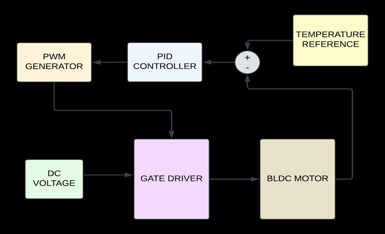
The system as shown in the Fig 1, begins with the Temperature Reference block, which is a critical componentfordeterminingthedesiredspeedoftheBLDC motor. In this application, the temperature reference is likelyderivedfromatemperaturesensorsuchastheLM35, which measures the ambient or system temperature. This reference provides a target temperature that is used to adjustthemotorspeedtoachievecooling
Thesummingblocksubtractsthefeedbacksignalfromthe temperature reference to compute the error signal. The errorsignalrepresentsthedifferencebetweenthedesired speed(basedonthetemperaturereference)andtheactual motor speed. This difference is crucial for adjusting the motor'soperationtoalignwiththedesiredconditions.
2.3
The PID Controller, or Proportional-Integral-Derivative controller, is a critical component in control systems for achieving precise and stable regulation of various processes. In the context of this architecture, the PID controlleradjuststhemotorspeed basedonthedifference between the desired temperature and the actual motor speed. The Proportional term directly responds to the current error by producing an output that is proportional to the error signal, providing an immediate corrective action. The Integral term addresses any accumulated past errors bysummingthem over time, effectively eliminating anyresidualsteady-stateerrorthatmightpersistafterthe proportionalaction
This helps ensure that the system reaches and maintains
the target speed. Meanwhile, the Derivative term predicts futureerrorsbyconsideringtherateofchangeoftheerror signal,whichallowsthesystemtopreemptivelycounteract potential overshoot and oscillations, enhancing system stability.Bycarefullytuningtheproportional,integral,and derivativegains,thePIDcontrollerdynamicallyadjuststhe motor speed, ensuring that the error signal is minimized. This process enables the motor to operate at the optimal speed to maintain the desired temperature, providing effectivecontrolfortemperature-sensitiveapplications.
The PWM Generator takes the output from the PID controller and converts it into a Pulse Width Modulated signal. PWM is a technique used to control the amount of powerdeliveredtoanelectricalload,inthiscase,theBLDC motor. The duty cycle of the PWM signal (the ratio of the on-timetothetotalperiodofthesignal)directlycorrelates with the motor speed. A higher duty cycle means more powerisdeliveredtothemotor,increasingitsspeed,while a lower duty cycle decreases the power and slows the motor.
The Gate Driver is an interface between the PWM signal from the PWM generator and the BLDC motor. It acts as a poweramplifier,capableofdeliveringtherequiredcurrent and voltage levels to the motor's windings based on the PWM signal. Gate drivers are essential for effectively switching the power transistors (such as MOSFETs or IGBTs)thatcontrolthemotorphases.InaBLDCmotor,
International Research Journal of Engineering and Technology (IRJET) e-ISSN: 2395-0056
Volume: 11 Issue: 08 | Aug 2024 www.irjet.net p-ISSN: 2395-0072
precise control of these switches is necessary for maintainingsmoothandefficientmotoroperation.
2.6 BLDC Motor
TheBLDCMotor(BrushlessDCMotor)isthefinalactuator in this control system.Unlike traditional DC motors,BLDC motors do not have brushes. Instead, they use electronic commutationtoswitchthecurrentinthemotorwindings, improvingefficiencyandreliability.ThespeedoftheBLDC motor in this system is regulated based on the input from the gate driver, which is controlled by the PWM signal generatedinresponsetothetemperaturereference.
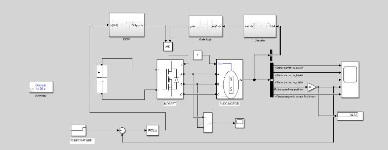
ThesimulationdiagraminFig2,appearstodepictacontrol system for a Brushless DC (BLDC) motor, focusing on temperature-based speed control using a ProportionalIntegral-Derivative(PID)controller.
3.1 PID controller
The PIDcontrolleradjusts themotorspeed basedon the error between the desired temperature and the actual temperaturemeasured bythe sensor. The PID controllawisgivenby,
( ) ( ) ∫ ( ) ( )……………(1)
where,
( )isthecontroloutput
3.2 PWM generation
The Pulse Width Modulation (PWM) signal is generated based on the control output u(t) from the PID controller. The duty cycle DDD of the PWM signal determines the averagevoltageappliedtothemotor, ……………………………………………………....(2)
where, istheaveragevoltageappliedtotheBLDCmotor isthedutycycleofthePWMsignal(0 ) isthesupplyvoltage
3.3BLDC
The BLDC motor's dynamics are modeled by the electrical and mechanical equations. The stator phase voltage equationforeachphasecanbeexpressedas, …………………………………………….(3)
where, isthephasevoltageappliedtothestatorwinding.
Listheinductanceofthestatorwinding.
Ristheresistanceofthestatorwinding. isthestatorcurrent. isthebackelectromotiveforce(EMF).
( ) is the error between the desiredtemperatureandthemeasuredtemperature and are the proportional, integral and the derivativegainsrespectively
International Research Journal of Engineering and Technology (IRJET) e-ISSN: 2395-0056
Volume: 11 Issue: 08 | Aug 2024 www.irjet.net p-ISSN: 2395-0072
ThebackEMF foreachphaseisproportionaltotherotor speed , ……………………………………………(4)
where is the back EMF constant of the motor.
The mechanical equation governing the motor’s speed is: ………………………………(5)
Thefeedbackmechanisminvolvesmonitoringthe motor'sspeedandcurrenttoadjustthePWMsignal accordingly.Therotorspeed andstatorcurrents arefedbackintothecontrolsystem:
=f(hallsignals)
=measuredcurrentsfromsensors
ThesefeedbacksignalsareusedbythePIDcontrollerto adjustthePWMdutycycleandensurethatthemotor speedrespondscorrectlytothetemperaturevariations.
The system operates by continuously adjusting the speed of a BLDC motor based on temperature feedback to maintain a desired temperature. It begins with the temperature reference, which sets the target temperature forthesystem.Thistargetiscomparedtotheactualmotor speed, generating an error signal that reflects the difference between the desired and actual speeds. This errorsignalisthenprocessedbythePIDcontroller,which calculates the necessary adjustment to minimize the error by tuning the proportional, integral, and derivative components.ThePIDcontrolleroutputisconvertedintoa PulseWidthModulation(PWM)signal,whichregulatesthe powerdeliveredtothemotorbycontrollingthedutycycle ofthesignal.ThegatedriverreceivesthisPWMsignaland amplifies it to drive the motor's phases with the appropriate current and voltage levels. As a result, the motor speed is adjusted according to the PID controller's output to match the temperature reference. The system continuously monitors the motor speed and temperature, repeatingthisprocesstoensurethemotoroperatesatthe optimal speed to achieve and maintain the desired temperature,ensuringeffectivetemperaturecontrol.
The waveform shown in the Fig 3 is the phase currents of a BLDC motor under speed control, with each phase current shifted by 120 degrees, indicating proper commutation. The trapezoidal shape and consistent magnitudesuggeststablemotoroperation,whilethesmall fluctuations are due to PWM control used for adjusting motorspeed.Overall,thewaveformsconfirmbalancedand efficient BLDC motor performance under speed control conditions.
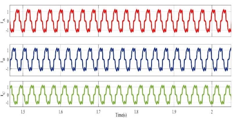
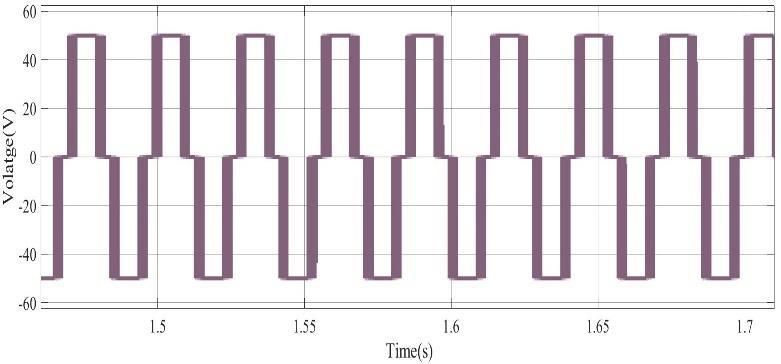
Fig 4 shows the phase voltage of the BLDC motor that is measuredbetweenphaseAandphaseB.
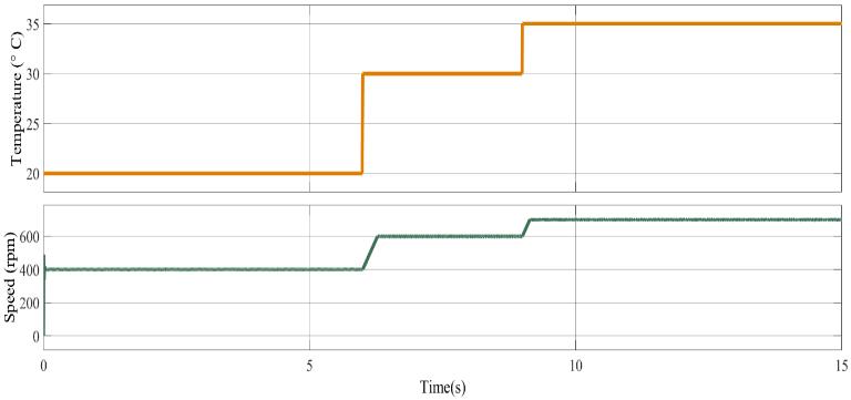
Fig5,showsthelinearchangeofthetemperaturevsspeed graph,as the temperaturechanges the speed of the motor changes. The figure shows how the motor speed changes withtemperature,illustratingthesystem'sresponseasthe temperature rises. This relationship gives an understanding of the temperature-based control of the BLDCmotor.Figure,depicts thebackEMFwaveformofthe BLDC motor , giving insight into the motor's electrical behaviorduringoperation.Thefigure displaysthecurrent waveformsforphasesA,B,andC,showinghowthecurrent isdistributedacrossthemotor'sphases.
International Research Journal of Engineering and Technology (IRJET) e-ISSN: 2395-0056
Volume: 11 Issue: 08 | Aug 2024 www.irjet.net p-ISSN: 2395-0072
The performance evaluation of the BLDC motor under temperature-based speed control reveals a high degree of operational efficiency. The phase currents exhibit proper commutation,witheachphaseshiftedby120degrees,and stable trapezoidal waveforms, indicative of consistent motoroperation.ThephasevoltagebetweenphasesAand B further corroborates the motor's stable behavior during operation. A linear relationship between temperature and motor speed is observed, highlighting the system's responsive adjustment of speed in accordance with temperature variations. These findings substantiate the effectiveness of the temperature-based speed control mechanism in maintaining the motor's balanced and efficientperformance.
[1] Vern Shen Chin, P., Teo, G., Zulfika, M., Ibrahim, M., Fuad, W.A., Othman, W., & Wahab, A.A. (2019). Development of Low-Cost Temperature Sensing Fan using Mapping Method on Arduino Uno and LM35 TemperatureSensor.
[2] Kumar,P.H.,&Somasekhar,V.T.(2023).AnEnhanced Fault-Tolerant and Autoreconfigurable BLDC Motor DriveforElectricVehicleApplications. IEEE Journal of Emerging and Selected Topics in Industrial Electronics, 4,368-380.
[3] Dakheel, H.S., Abdullah, Z.B., & Shneen, S.W. (2023). Advanced optimal GA-PID controller for BLDC motor. Bulletin of Electrical Engineering and Informatics.
[4] Babu, N.R., Sai, S.S., Kumar, U., Chenchireddy, K., Kumar, K.T., & Naveen, M. (2023). Optimized Speed Control of BLDC Motor Control by using PID and ANFIS. 2023 International Conference on Sustainable Communication Networks and Application (ICSCNA), 653-658.
[5] Mahmud, M., Islam, M.R., Motakabber, S.M., Satter, M.D., Afroz, K.E., & Ahasan Habib, A. (2022). Control Speed of BLDC Motor using PID. 2022 IEEE 18th International Colloquium on Signal Processing & Applications(CSPA),150-154.
BIOGRAPHIES

S.G SRIVANI (Senior Member, IEEE) received the ME degree from Bangalore University and Ph. D degree from NITK, Surathkal, is currently the Professor and HOD of EEE, RV CollegeofEngineering, Bengaluru.

Sahana R received the B.E. degree in EEE from Visvesvaraya Technological University, Belagavi, She is currently pursuing her M Tech in Power Electronics in RV College of Engineering,Bengaluru.