
International Research Journal of Engineering and Technology (IRJET) e-ISSN:2395-0056
Volume: 11 Issue: 06 | Jun 2024 www.irjet.net p-ISSN:2395-0072
International Research Journal of Engineering and Technology (IRJET) e-ISSN:2395-0056
Volume: 11 Issue: 06 | Jun 2024 www.irjet.net p-ISSN:2395-0072
Krishna Jayachandran1,Alna Ashok2, Tanha Nazer3 , Thalif Nazer4 , Dr Prathibha Sudhakaran5
1Student, Dept. of ECE, Muthoot Institute of Technology and Science, India
2Student, Dept. of ECE, Muthoot Institute of Technology and Science, India
3Student, Dept. of ECE, Muthoot Institute of Technology and Science,India 4Student, Dept. of ECE, Muthoot Institute of Technology and Science, India
5Asst.Professor, Dept.of ECE, Muthoot Institute of Technology and Science
Abstract- This research suggests a novel method for using arrays of Microstrip Patch Antennas (MPA) to maximize wireless connection in WLAN (Wireless Local Area Network) applications. The main objective of the paper is to design and implement the microstrip patch array antenna of 2.4Ghz for wireless application. Signal degradation, interference, and restricted coverage are common problems for older WLAN systems. By improving coverage, reducing interference, and boosting signal strength, the MPA arrays seek to address these problems. This study discusses the design, implementation, and performance evaluation of MPA arrays and shows how effective they are at enhancing WLAN connectivity.
Keywords: WLAN, Microstrip Patch Antennas[MPA], Connectivity, Antenna Arrays, Wireless Communication, HFSS
Inmoderntimes,wirelesslocalareanetworks,orWLANs,are ubiquitous because they offer lag-free connectivity for a variety of uses, including file sharing, multimedia streaming, and internet access. The difficulties in maintaining dependableandhigh-performanceWLANsaregrowingalong with the demand for wireless access, especially in crowded urbanareas,sizableofficebuildings,andpublicareas.
Traditionally,WLANshavereliedonsingle-sourceantennasto transmit and receive signals, which often resulted in limited coverage, capacity constraints, and susceptibility to interference. These limitations have spurred research and development efforts aimed at improving WLAN connectivity throughinnovativeantennatechnologies.
One such promising approach is the utilization of MultiSource Antennas (MSA), which offer significant advantages over traditional single-source antennas. Unlike single-source antennas, MSAs consist of multiple radiating elements that cantransmitor receivesignalssimultaneouslyfromdifferent spatiallocations.Byharnessingthespatialdiversityprovided
by MSA arrays, it is possible to enhance signal strength, increasecoverage,andmitigateinterferenceeffectively.
The objective of thispaper isto explore the potential of MSA arrays in maximizing wireless connectivity for WLAN applications. This includes investigating the design considerations, implementation challenges, and performance evaluation of MSA-based WLAN systems. By leveraging the capabilities of MSA arrays, we aim to address the existing limitations of traditional WLAN setups and pave the way for morerobustandefficientwirelesscommunicationnetworks.
The objective of this study was to design and characterize a wideband microstrip patch antenna with a single slot operating at 2.4 GHz specifically for WLAN (Wireless Local Area Network) applications. The aim was to enhance the impedance bandwidth compared to conventional patch antennas while maintaining a compact and low-profile design. The introduction of the single slot in the radiating patch, along with optimized dimensions, was intended to achieve this objective, enabling the antenna to cover a broader frequency range suitable for various wireless communication applications beyond WLAN The study also aimed to validate the simulated performance through experimental results, thus confirming the antenna's suitability for practical implementation in diverse communication systems.[1]This paper presents the design, fabrication and testing of a rectangular circular patch array 1x8microstripantennaoperatingat1800MHzfrequencyfor amplifying 4G cellular signals. The 4G technology provides high bandwidth of 75 MHz and operates in the 1800 MHz band. In receiving and transmitting information signals, the 4G system requires antennas to radiate the electromagnetic waves. However, the transmitted signals can get attenuated duetofactorslikeair,buildingwallsandweatherconditions. To overcome this signal degradation, a device is needed to boost the signal strength from the evolved Node B (eNodeB) transmitterssothatuserscanreceivegoodsignalquality.The
International Research Journal of Engineering and Technology (IRJET) e-
Volume: 11 Issue: 06 | Jun 2024 www.irjet.net p-ISSN:2395-0072
proposed antenna design aims to serve as such a signal repeater device. The antenna parameters like return loss, VSWR, gain and radiation pattern are calculated and optimized through theoretical analysis and simulations. The designed antenna is then fabricated and its performance is experimentallymeasured.Thetestresultsshowareturnloss of-20.3dB,VSWRof1.208,gainof7.32dBandunidirectional radiation pattern, meeting the desired specifications. Finally, the antenna is tested as a 4G signal amplifier with various cellular providers in different locations, demonstrating its capability to significantly improve the received signal strength. [2] The objective of this study is to design and simulateedge-fedmicrostrippatchantennaarraysoptimized for bistatic radar applications, specifically leveraging the Frequency Modulated Continuous Wave (FMCW) technique for simultaneous transmission and reception to analyze weather and climate patterns. The focus is on designing and simulating single patch, 1x4, 2x2, and 4x4 edge-fed microstrip patch antenna arrays operating at 1.48 GHz using an FR4 dielectric substrate. The design parameters include parallel feed connections and an inter-element spacing of 0.8λinbothhorizontalandverticaldirections.
Using CST Microwave Studio, the study aims to assess the performance of the 4x4 array configuration by analyzing key parameters such as return loss, bandwidth, directivity, and radiation pattern, with the ultimate goal of determining the suitability of the antenna arrays for bistatic radar applications. [3] The objective of this paper is to present the designandanalysisofarectangularmicrostrippatchantenna usingHFSSsoftwarefor2.4GHzWirelessLocalAreaNetwork (WLAN) applications. The antenna utilizes an FR-4 dielectric substrate with specified dimensions. Design equations are provided to calculate the patch and substrate dimensions. HFSS simulation results including return loss, voltage standing wave ratio (VSWR), 2D and 3D radiation patterns arepresentedandanalyzed.Thedesignedantennaachievesa returnlossof-12.0505dBat2.4GHzwithanomnidirectional radiation pattern suitable for WLAN. The authors conclude that the low-profile microstrip patch antenna with a simple microstripfeedlinecanbeeasilyfabricatedanddeployedfor 2.4 GHz WLAN applications.[4] This paper presents the designandperformanceanalysisofdifferentmicrostriparray antenna configurations with optimized parameters for Xband applications around 10 GHz frequency. Microstrip antennas offer advantages like low-profile, light-weight, simple construction and compatibility with printed circuit technology, making them suitable for modern wireless communication systems. However, their key limitations are narrow bandwidth and low power handling capability. Arranging the microstrip elements in an array configuration can overcome these limitations and provide high gain, wide bandwidth and improved efficiency. The paper investigates three array configurations - series feed, corporate feed, and
combined corporate-series feed networks. The design parameterslikedielectricsubstratematerial,substrateheight and operating frequency are optimized to achieve compact dimensions as well as desirable performance metrics. The TaconicTLY-5substratewithpermittivityof2.2andheightof 1.588mmisused.
Simulation studies are carried out using SONNET software. Forthe4x1seriesfeedarrayat10GHz,againof11.97dBand return loss of -4.21 dB are obtained. The 4x1 corporate feed array exhibits a higher gain of 14.14 dB and significantly lowerreturnlossof-25.456dBat10GHz.Thecombined4x2 corporate-series feed array provides the highest simulated gainof17.48dBwhilemaintainingamoderatereturnlossof7.55 dB. It merges the advantages of reduced feed network losses from series feed and better directivity from corporate feed. The designed antennas operating around 10 GHz are potential candidates for X-band applications like satellite communications, radar, wireless systems due to their simple structure, ease of fabrication, high gain and efficiency. The combined corporate-series feed array offers the best overall performanceamongthethreeconfigurationsstudied.[5]This paper presents the design and development of an 8x1 microstrip patch antenna array operating in the X-band frequency range for military and satellite communication applications. The antenna array is designed using a series corporate feeding technique with quarter-wave transformers and T-junction power dividers to achieve enhanced gain, directivity, bandwidth, and return loss. The design process starts with a single rectangular microstrip patch antenna element on an FR-4 substrate. Subsequently, 2x1, 4x1, and 8x1 antenna arrays are designed by arranging the patch elements linearly and employing series corporate feeding networks. The simulated results obtained using the HFSS software demonstrate that the 8x1 antenna array achieves a maximum gain of 14.56 dB at 10 GHz, an impedance bandwidthof86.72%,andanefficiencyof99%.Theradiation patterns,reflectioncoefficients,andgainperformancesofthe different antenna array configurations are presented and compared.Theproposed8x1antennaarrayexhibitsdirective radiation characteristics and an improved peak gain compared to existing designs, making it suitable for applications such as downlink X-band satellite communication, military applications, WLAN, WiMAX, and vehicularcommunication[6]
This paper presents the design of a 3x3 rectangular microstrip patch antenna array operating in the Ku-band frequency range from 12 to 18 GHz. The antenna array is designedandsimulatedonanFR4substratewithadielectric constant of 4.4using the finite element method(FEM) based HFSS 14.0 software. The array elements are spaced at a distance of λ/2, and the excitation technique used is probe feeding. The design considerations,including the dimensions
International Research Journal of Engineering and Technology (IRJET) e-ISSN:2395-0056
Volume: 11 Issue: 06 | Jun 2024 www.irjet.net p-ISSN:2395-0072
of the substrate, patch elements, and feed configuration, are provided. The simulated results demonstrate that the proposed 3x3 antenna array achieves a maximum gain of 17.29dBattheoperatingfrequencyof13.33GHz.Thereturn lossatthisfrequencyisfoundtobe-13.33dB,andthevoltage standing wave ratio (VSWR) is 0.7807, indicating good impedance matching. The radiation characteristics, including the 3D polar plot, directivity, radiation pattern, and E-field and H-field radiation patterns, are presented and analyzed. The simulated results show that the proposed antenna array exhibitsgoodperformanceintermsofreturnloss,VSWR,and gain, making it suitable for Ku-band applications in wireless communicationsystems[7].
The design methodology for the microstrip patch antenna arrayinvolvesseveralkeysteps:
3.1 Substrate Selection
The choice of substrate material plays a crucial role in determining the performance of the antenna array. Factors such as dielectric constant, loss tangent, substrate thickness, and cost need to be considered. In this study, FR-4 substrate material with a dielectric constant of 4.4 and a thickness of 1.6mm was selected due to its widespread availability and lowcost.
3.2 Patch Design:
Thedimensionsofthemicrostrippatchantennaelementsare determined based on the desired operating frequency of 2.4GHz.
Various analytical formulas and empirical equations are availableforcalculatingthedimensionsofthepatchantenna, including the length, width, and feed location. However, numericalelectromagneticsimulationtoolssuchasHFSSare often employed foraccurate andefficientoptimizationofthe patch geometry to achieve desired performance parameters suchasimpedancematchingandradiationcharacteristics
Radius of circular patch: Theradius(a)ofacircular patchinscribedinhexagonalmicrostrippatchcanbe determined using empirical formulas or simulation toolsbasedonthedesiredresonantfrequency.
where:f–Resonantfrequency
Circular patch effective radius: Theeffectiveradius (����) of the substrate can be estimated using the followingformulaforamicrostriptransmissionline,
Length of sides of hexagonal patch: The actual length (S) of the patch can be calculated by consideringitseffectiveradius(����).
The numerical connection between round fix reception apparatus sweep and hexagonal fix receiving wire side is givenby
Sidesofhexagonalpatch,
Thegroundplanewidthandlengthare225mmx60mm,the sidesofthehexagonalfixis16.393mm.
The number of elements in the antenna array and their spatial arrangement significantly impact the overall performance of the array. Common array configurations include linear, circular, planar, and conformal arrays. In this study, a linear array configuration with four elements was chosen for simplicity and ease of analysis. The spacing between the elements is optimized to achieve the desired radiationpatternandimpedancecharacteristics.
Array Factor: The Array Factor (AF) for an N elementlineararrayisgivenby,
International Research Journal of Engineering and Technology (IRJET) e-ISSN:2395-0056
Volume: 11 Issue: 06 | Jun 2024 www.irjet.net p-ISSN:2395-0072
Where: θ – Observation angle with respecttothearrayaxis d–spacingbetweenelements
For Broadside array θ = 0 because maximum radiation is expected in the direction perpendicular tothearray.Therefore,theequationsimplifiesto:
Comprehensive electromagnetic simulation using software tools such as HFSS is performed to analyze the performance of the antenna array. The simulation includes characterization of the radiation pattern, gain, directivity, impedancematching,bandwidth,andefficiency.
Parametric studies are conducted to optimize the design parametersandachievethedesiredperformanceobjectives.
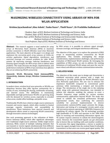
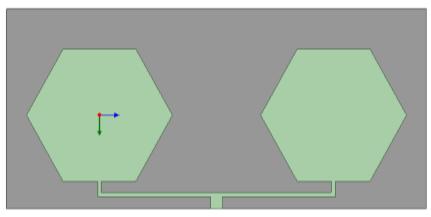
Initially we have designed single hexagonal microstrip patch antenna.Furtherwehavedesigned2x1&4x1arrayantenna
=��
This means that the broadside direction is enhanced by a factorofNcomparedtotheradiationfromasingleelement.
Element Spacing: Forabroadsidearray,theelement spacing(d)istypicallyhalfofthewavelength:
Thefeednetworkoftheantennaarrayisdesignedto provideproperphasingandimpedancematchingfor the individual elements. Various feeding techniques, suchascorporatefeed,seriesfeed,andparallelfeed, can be employed depending on the specific requirements of the application. The feed network design is crucial for achieving uniform excitation of the array elements and minimizing mutual coupling effects.
Microstrip Width (����): The Microstrip line width foracharacteristicimpedance(��0):
Spacingbetweenpatches 68.25mm 100ohmfeedlinewidth 0.7mm 70.7ohmfeedlinewidth 1.6mm
50ohmfeedlinewidth 3mm

After designing and fabricating, the next step was antenna parametertesting.Themeasuredparameterwerereturnloss, VSWR, directivity and gain. Based on simulation result the value of return loss was obtained as -349476dB and from testingresultthevaluewasobtainedas-11.185
By comparing the results of a single element and array element plot, we can ensure, with increasing elements the enhancement of return loss, gain, VSWR and radiation pattern performance is done and the proposed antenna potentially serve as a best option for short range 2.4Ghz of bandwirelesscommunicationapplication
International Research Journal of Engineering and Technology (IRJET) e-ISSN:2395-0056
Volume: 11 Issue: 06 | Jun 2024 www.irjet.net p-ISSN:2395-0072
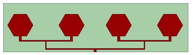
Fig 4 Gainplot
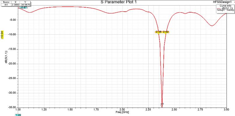
Fig 5 S-Parameter
From fig 4, gain of the antenna is 7.1dB, Fig 5 represents sparameter.Basedonsimulationresultthevalueofreturnloss wasobtainedas-34.9476dB.
6.CONCLUSION
In summary, this paper presents a detailed study on design and simulation of a microstrip patch antenna array for 2.4GHz wireless communication. The array configuration offers significant improvements in gain, directivity, and radiation pattern control over single-element antennas. Utilizing HFSS simulation software, the design achieves efficient radiation characteristics with a return loss of349476dBat2.4GHz.Theoptimizedresonanceatthedesired frequency is facilitated by a microstrip feed line, ensuring adequate bandwidth. Simulation results align closely with design objectives, affirming the suitability of the proposed antenna array for modern wireless communication systems. This study highlights the importance of advanced simulation techniquesinachievingoptimalantennaperformance.
ACKNOWLEDGEMENT
We extend our sincerest gratitude to Professor Dr Prathibha Sudhakaranforherinvaluablecontributions,adeptguidance, unwavering encouragement, and wholehearted cooperation throughout our endeavor. Our heartfelt appreciation goes to Muthoot Institute of Technology and Science for their
support and encouragement in permitting us to pursue our research on MAXIMIZING WIRELESS CONNECTIVITY USING ARRAYS OF MSA FOR WLAN APPLICATION. We also wish to express our gratitude to all lecturers who have directly or indirectly assisted us in our project. Additionally, we extend our thanks to our parents and friends for their steadfast cooperationandsupport.
[1] GurudevandM.Bakhar,"DesignandImplementation of Microstrip patch Antenna Arrays for 2.4 GHz Applications," Research Square, 11-Nov-2022. [Online]. Available: https://doi.org/10.21203/rs.3.rs-994633/v1. [Accessed:05-Mar-2024]
[2] T. Supriyanto, R. K. Nurinsani, and T. Firmansyah, "Design of Microstrip Rectangular Circular Array Antenna1x8atFrequencyof1800MHzfor Increase Power of 4G signal," J. Phys. Conf. Ser., vol. 1364,no.1,p.012026,Nov.2019
[3] K. Mydhili, P. Parvathi, and K. Prasanthi, "Design and simulation of edge fed microstrip patch antenna array,"inProc.SecondInt.Conf.I-SMAC(IoTin Social,Mobile, Analytics and Cloud), Palladam,India, 2018,pp.356-360.
[4] E. Krishna Kumar, C. N. Marimuthu, and E. Manickavalli, "A Microstrip Patch Antenna Design usingHFSSforWirelessLocalAreaNetwork(WLAN) Applications at 2.4GHz Frequency," International Journal of Mechanical Engineering, vol. 6, no. 3, pp. 1169-1172,Dec.2021.
[5] M. T. Ishtaique-ul Huque, M. K. Hosain, M. S. Islam, and M. Al-Amin Chowdhury, "Design and Performance Analysis of Microstrip Array Antennas with Optimum Parameters for X-band Applications," International Journal of Advanced Computer Science and Applications (IJACSA), vol. 2, no. 4, pp. 81-87, 2011.
[6] A. M. J. Kinol and A. S. Nisha, "Development and design of 8x1 micro strip antenna array for military/satellite communication," Int. J. Eng. Technol.,vol.7,no.4.36,pp.409-413,2018.
[7] V. Midasala and P. Siddaiah, "Microstrip patch antenna array design to improve better gains," ProcediaComput.Sci.,vol.85,pp.401-409,2016.