
International Research Journal of Engineering and Technology (IRJET) e-ISSN: 2395-0056
Volume: 11 Issue: 06 | Jun 2024 www.irjet.net p-ISSN: 2395-0072
International Research Journal of Engineering and Technology (IRJET) e-ISSN: 2395-0056
Volume: 11 Issue: 06 | Jun 2024 www.irjet.net p-ISSN: 2395-0072
Manthan Patel1 , Pinank Parikh2 , Pratham Panchal3, Shardul Lokhande4
[1]-[4]Student, Dept. Of Mechanical Engineering, AP Shah Institute of Technology, Thane, Maharashtra, India
Abstract - The objective of this study is to optimize the design parameters of a parabolic trough solar collector system to maximize its thermal efficiency. Specifically, the project aims to investigate the impact of various factors such as aperture area, geometrical concentration ratio, absorber tube diameter, and tracking mechanism on the performance of the collector. The parabolic trough solar collector, with its wide temperature range up to 400°C, is pivotal in concentratedsolar power technology.
Key Words: Parabolic trough solar collector (PTSC), Aperture area, Rim angle, Aperture width, Trough length, Thermal losses
1.INTRODUCTION
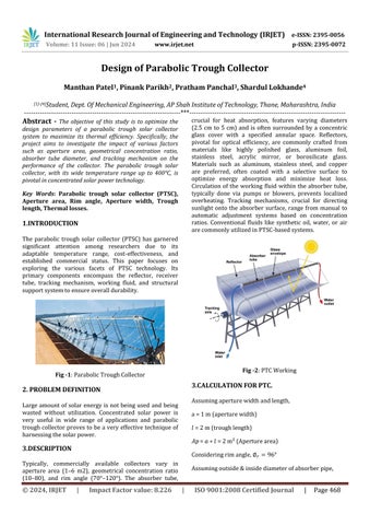
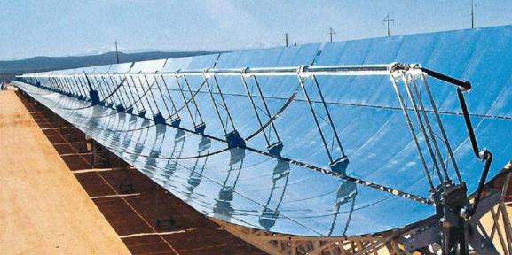
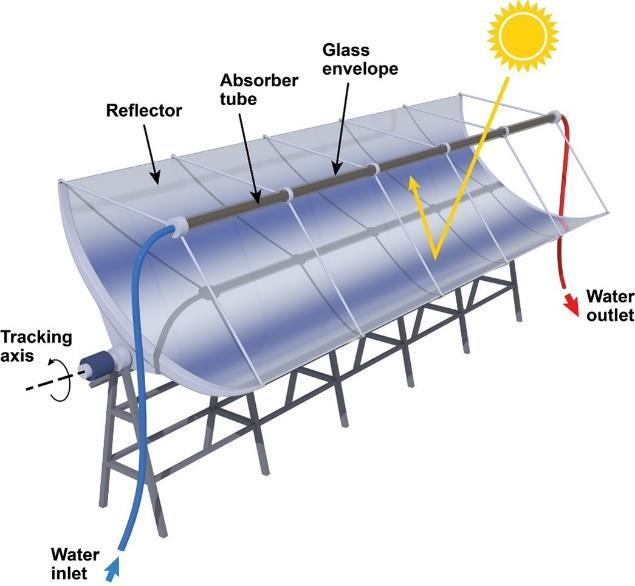
The parabolic trough solar collector (PTSC) has garnered significant attention among researchers due to its adaptable temperature range, cost-effectiveness, and established commercial status. This paper focuses on exploring the various facets of PTSC technology. Its primary components encompass the reflector, receiver tube, tracking mechanism, working fluid, and structural supportsystemtoensureoveralldurability.
2. PROBLEM DEFINITION
Large amount of solar energy is not being used and being wasted without utilization. Concentrated solar power is very useful in wide range of applications and parabolic troughcollectorprovestobea veryeffectivetechnique of harnessingthesolarpower.
3.DESCRIPTION
Typically, commercially available collectors vary in aperture area (1–6 m2), geometrical concentration ratio (10–80), and rim angle (70°–120°). The absorber tube,
crucial for heat absorption, features varying diameters (2.5 cm to 5 cm) and is often surrounded by a concentric glass cover with a specified annular space. Reflectors, pivotal for optical efficiency, are commonly crafted from materials like highly polished glass, aluminum foil, stainless steel, acrylic mirror, or borosilicate glass. Materials such as aluminum, stainless steel, and copper are preferred, often coated with a selective surface to optimize energy absorption and minimize heat loss. Circulation of the working fluid within the absorber tube, typically done via pumps or blowers, prevents localized overheating. Tracking mechanisms, crucial for directing sunlight onto the absorber surface, range from manual to automatic adjustment systems based on concentration ratios. Conventional fluids like synthetic oil, water, or air arecommonlyutilizedinPTSC-basedsystems.
3.CALCULATION FOR PTC.
Assumingaperturewidthandlength, a=1m(aperturewidth) =2m(troughlength) = =2m²(Aperturearea)
Consideringrimangle,
Assumingoutside&insidediameterofabsorberpipe,
International Research Journal of Engineering and Technology (IRJET) e-ISSN: 2395-0056
==3.75cm=0.375m
=3.25cm=0.325m
Wallthickness=0.5cm=0.005m
Tofindfocallength, ( ) √ ( )
The equation for PTSC depth or height (H) can be obtained by putting in the equation of parabola ,Thusweobtain:-
Now,Thermalefficiencyofsolarcollector, th
Whereusefulenergyisgivenby, ( )
Now,
Effectiveaperturearea ( ) ( )
Surfaceareaofconcentratorisgivenby,
ReflectororTroughRadius, ( )
Geometrical concentration ratio (C) is one of the important geometrical parameters for concentrating type ofsolarcollectorwhichremainsconstantoncethesystem gets manufactured. It signifies the system’s ability to concentratesolarenergy,anditsvaluevariesfromunityto 105 (( ) ( ))
Theoreticalmaximumconcentrationratio, ( )
Where,
=0.2670 (halfoftheanglesubtendedbysunonearth)
Where, = 4184 JKg-1 K-1 (Specific capacity of fluid which is water)
T=( )K
Nowhere,massflowrate,
Where, =Densityoffluid(water)=1000Kg/m3
Crosssectionalflowareaofpipe,
Considering a full flow pipe therefore Hydraulic Diameter ( )willbesameasabsorbertubeinternaldiameter,
Wettedperimeter( )isgivenby,
Volume: 11 Issue: 06 | Jun 2024 www.irjet.net p-ISSN: 2395-0072 © 2024, IRJET | Impact Factor value: 8.226 | ISO 9001:2008
Now,massflowrate, =
Considering, =averagevelocityoffluid =DensityoffluidKg/m3
Now,Reynold'snumberisgivenas =
Now,usefulenergyisgivenby ( )
ToCalculateAvailableEnergy,
International Research Journal of Engineering and Technology (IRJET) e-ISSN: 2395-0056
Volume: 11 Issue: 06 | Jun 2024 www.irjet.net p-ISSN: 2395-0072
Where,
= Aperturearea
= BeamRadiation
BeamRadiationisgivenas, ( ( ) )
Where, areconstantsgivenas ( ) ( ) ( )
=Altitudeofobserverinkm
Now, ( ( ))
Where,
=Extra-terrestrialhourlyBeamradiation
=1367Wm-2 (SolarConstant)
=1-365(Adaynumberinyear)
Now,zenithangleisgivenby, ( ) ( ) ( ) ( ) ( ) ( )
Where,
=declinationangle
=hourangle
=latitudeoflocation
Also,
Presuming Solar noon at 12 pm , = 0° Earth rotates aftereachhourby15°,Thereforeifweconsider1pmthan thehouranglewillbe15
Thus with the Aperture area which was assumed as 2 m2 wewillobtainanAvailableenergy inKwwhichwillbe generated in that area having Beam radiation ( ) whose
value will be different according to different locations. Therefore to generate a temperature difference ( ), isusefulenergyi.e.requiredEnergy.
To generate this required energy, the required Aperture area( )willbe, ( )
Thusafterobtainingtherequiredaperturearea,thelength towidthratiocanbekeptortakenas10:3.
Remaining parameters can be obtained easily from the formulasmentionedabovetoconstructaPTCforrequired generationofenergy.
NowfrictionfactorgivenbyFilonenkorelationship, ( )
Weknowthat,
Pr=6.9 (forwater)
Meanfluidtemperatureisgivenby,
Now from empirical relation of Dittus-Boelter in smooth surfacetube, ( )
Where,
n=0.4&0.3(forheatingandcoolingfluidrespectively)
Applicableforgenerally:0.6 Pr ,Re andfully developedflowi.e. (10-60).
Meantemperatureoftubewall,
Now, Nusselt number from Sieder & tater equation for largetemperaturevariationisgivenby, ( )
Now pressure drop can be calculated with the help of relationwithfrictionfactor,
© 2024, IRJET | Impact Factor value: 8.226 | ISO 9001:2008 Certified Journal | Page470
International Research Journal of Engineering and Technology (IRJET) e-ISSN: 2395-0056
Volume: 11 Issue: 06 | Jun 2024 www.irjet.net p-ISSN: 2395-0072
AndHeadduetofriction( )isgivenby,
Nowextra powerrequired bypumpduetopressuredrop isgivenby,
Where,
=extrapowerrequiredbypump
=isentropicefficiency=80%(Assumed)
The friction factor can be evaluated & validated with Blasiusequation&Filonenkoequation,
Alsoabsorbedsolarheatfluxcanbeevaluatedas
Therefore, Thermal losses associated with absorber tube exteriorsurfacetoenvelopeinteriorsurface
Where and are heat losses due to convection and radiationrespectively ( ) ) ( )
Where, is the convective coefficient of heat transfer betweenabsorberandglassenvelope.
for,2x104 < <2x10⁶
Now, for convective transfer between fluid and tube, can beevaluatedbyenergybalanceequation
( ) ( )
WhereAs=Internalsurfacearea= L
Optical efficiency is a measure of the extent of the perfectness of the system, which is represented mathematicallyasfollows,
opt ( )
Where,
r= reflectivity of reflector= 90% (Assumed for aluminum foil)
=interceptfactor=1(Assuming100%ofabsorbertubeis coveredbysunlight)
T=transmissivityofcover=80%(forglass)
=absorptivityofabsorber=1(blackpaint)
( )=1
From energy balance equation on absorber tube by assumingsteadystatecondition
Absorbedsolarheatflux=Usefulenergy+Thermallosses
The relationship between and effective thermal conductivity can be obtained by equating expressions for heatexchangeasfollows ( )
( ) ( )
Therefore,Heatloss canberearrangedas eff ( ) ( ) ( ) ( )
Where,
=Temperature attained by cover = 42 (at noon assumed)
=Emissivityofcover=0.89(Forglass)
=Emissivityofabsorber=1(blackbody)
=Internaldiameterofenvelope
=Externaldiameterofabsorber
=Externaldiameterofenvelope
=Stefanboltzmanconstant=5.67x10⁻⁸ W/m2K4
Here, eff which is the effective thermal conductivity can beexpressedas eff ( ) ( )
Where,
International Research Journal of Engineering and Technology (IRJET) e-ISSN: 2395-0056
Volume: 11 Issue: 06 | Jun 2024 www.irjet.net p-ISSN: 2395-0072
=0.7491(Constant)
=Radialgap= ( )
TheRayleighnumbercanbepresentedas,
= = * ( )+
Where, Properties are taken at average temperature ( )
=kinematicviscosityoffluid
=coefficientofvolumetricexpansion
= Accelerationduetogravity= 9.81 m/s2
Similarly thermal losses from the glass envelope to the environmentcanbeevaluatedby, ( ) ( )
Where,
=Ambienttemperature
=Skytemperature
The convective coefficient of transfer of heat between glassenvelopeandenvironmentisobtainedas ind
Where, ind =3.7m/s
ACKNOWLEDGEMENT
This is to acknowledge Professor Sushrut Patankar for helping and guiding for the research of ‘Design of ParabolicTroughCollector’.
REFERENCES
[1] Abdulhamed A J, Adam N M, Ab-Kadir M Z A and Hairuddin A A 2018 Review of solar parabolic-trough collector geometrical and thermal analyses, performance, andapplicationsRenew.Sustain.EnergyRev.91822–31
[2] Ferna A 2010 Parabolic-trough solar collectors and theirapplications141695–721
[3] Upadhyay B H, Patel A J, Sadasivuni K K, Mistry J M, Ramana P V, Panchal H, Ponnamma D and Essa F A 2021 Design, development and techno economic analysis of novel parabolic trough collector for low-temperature
water heating applications Case Stud. Therm. Eng. 26 100978
[4]J.Macedo-Valenciaa,J.Ramírez-Ávilaa,R.Acostaa,O.A. Jaramillob and J.O Aguilara Design, construction and evaluation of parabolic trough collector as demonstrative prototype
[5]MayankLambaa*,SubhraDasbDesigningofParabolic TroughCollectorusingPlaneMirrors
© 2024, IRJET | Impact Factor value: 8.226 | ISO 9001:2008 Certified Journal | Page472