International Research Journal of Engineering and Technology (IRJET)
e-ISSN: 2395-0056
Volume: 11 Issue: 06 | Jun 2024
p-ISSN: 2395-0072
www.irjet.net
Research on the Effect of Horizontal Walkway Location Connecting Two High-Rise Buildings (G+20) Under Seismic Loading Chandan Ahir1, Prof. Neeraj Singh Bais2 1M.Tech Student, Structural and construction Engineering Department, Ballarpur Institute of Technology,
Maharashtra, India
2Assistant Professor, Structural and construction Engineering Department, Ballarpur Institute of Technology,
Maharashtra, India ---------------------------------------------------------------------***--------------------------------------------------------------------load response of the linked high-rise buildings. The influence Abstract - This study investigates the influence of the of the bridge's location is also analyzed. The buildings are evaluated for maximum displacement, maximum reactions, maximum bending moment (BM) results, and maximum base shear. The primary objective is to study the impact of the location of a horizontal walkway connecting two highrise buildings (G+20) under seismic loading. Dead load, live load, seismic load, and wind load are applied, and the design for beams and columns is obtained using STAAD.Pro. The study concludes that STAAD.Pro is a highly efficient and accurate tool for designing multistoried buildings, significantly saving time and ensuring precise designs.
location of a horizontal walkaway connecting to 4th floor, 8th ,12th and 16th floors of G+20 high rise building under seismic loading conditions. The horizontally connected structures are subjected to various seismic loading Conditions to evaluate how the walkways position influences the overall Dynamic behaviour and stability of the buildings. Using finite element Analysis (FEA), multiple scenarios with the walkway located at different Heights are modelled and analysed. Key performance indicators Such as story drift, base shear, and overall displacement are compared across Different configurations. The findings reveals that the walkway’s location Significantly affects the seismic performance of the connected buildings, with optimal placement reducing structural stresses and enhancing safety. This research provides valuable insights for architects and engineers in Designing more resilient horizontally connected high rise structures in Seismically active regions. This research focuses on the structural performance and dynamic behaviour of the buildings. When subjected to earthquake forces considering different locations of horizontal walk connected forces and height of the structures. In this connected building, The effect of sky bridge structural responses is examined as well. The building is analysed for the Max displacement, max reaction, max BM and max base shear. This analysis and modelling is done by using Staad pro software.
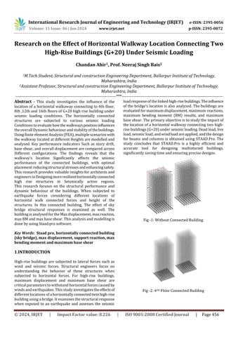
Fig -1: Without Connected Building
Key Words: Staad pro, horizontally connected building (sky bridge), max displacement, support reaction, max bending moment and maximum base shear
1.INTRODUCTION High-rise buildings are subjected to lateral forces such as wind and seismic forces. Structural engineers focus on understanding the behavior of these structures when subjected to horizontal forces. For high-rise buildings, maximum displacement and maximum base shear are critical parameters to withstand horizontal forces caused by winds and earthquakes. This study investigates the effects of different locations of a horizontally connected twin high-rise building using a bridge. It examines the structural response when exposed to an earthquake and assesses the seismic
© 2024, IRJET
|
Impact Factor value: 8.226
Fig -2: 4rth Floor Connected Building
|
ISO 9001:2008 Certified Journal
|
Page 456