
International Research Journal of Engineering and Technology (IRJET) e-ISSN: 2395-0056
Volume: 11 Issue: 06 | Jun 2024 www.irjet.net p-ISSN: 2395-0072
International Research Journal of Engineering and Technology (IRJET) e-ISSN: 2395-0056
Volume: 11 Issue: 06 | Jun 2024 www.irjet.net p-ISSN: 2395-0072
Vishvesh Jayswal1 , Aakash Suthar2 ,
1M. Tech Student, L.J. University, Ahmedabad
2Aakash Suthar, Head of Department, Structural Engineering Department, L.J. University, Ahmedabad, India. ***
Abstract: -Inadditiontoissueswithlandacquisition,tall buildingsarebecomingincreasinglycommon.Ingeneral,a linked tall building is a skyscraper or high-rise that is physicallyjoinedtooneormoreneighboringstructuresby bridges or other structural components. It provides customers with horizontal connection in addition to improving structural performance under lateral stresses. Variouslateralloadresistingsystemsandvibrationcontrol systems must be implemented in order to regulate the lateraldisplacementofatallbuilding.Thisstudycompares linear viscous dampers and shear wall systems in tall buildings. The study examines models of interconnected, (25-story) tall structures with varying skybridge and damper locations. Reduction of several reactions such as displacement,acceleration,storeydrift,etc.hasbeenproven tobemoresuccessfulintheconstructionsassociatedwith SkyBridgeanddampers.
Key Words: (Connected Tall Building), (Shear Wall), (Bracing), (Damper), (Seismic load) &(wind load)
1. INTRODUCTION: -
Abuildingisclassifiedasa"tallbuilding"by(IS:6700:2017) ifitsheightismorethan50metersbutlessthanorequalto 250meters.Thereisnosetstandardforwhatconstitutesa "tall" structure. "Super Tall Building" refers to a structure taller than 250 meters. [3] Towering structures known as skyscrapersareusuallyfoundincrowdedurbanareaswith expensive land. In the construction industry, lateral loadresisting devices are utilized to withstand lateral forces including wind and seismic forces. Shear wall structures, moment frames, braced frames, framed tube structures, diagrid structures, and so on are a few examples of these systems.Thesebuildingsareadditionallyprotectedfromthe effectsofoscillationsbyvibrationcontrol devices,suchas baseisolationsystemsanddampers.
A shear wall structure is a kind of building construction wherewallsareusedtoresistwindandseismicstressesand toofferlateral stability.Thesewalls,whicharefrequently seen in both tall and low-rise structures, are in charge of supportingcolumnsandverticalloads [1]
Thereactivityofstructurestodynamicloads,suchwindand earthquakes, is lessened by the employment of structural
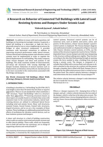
control systems. Structural control systems can be of numerous sorts, such as hybrid, semi-active, active, and passive.Inthisinstance,alinearviscousdamperapassive controlsystem isemployed. TheViscousDamperdiagram andmathematicalmodelaredisplayedin(Figures1(a)and 1(b). Passive vibration control systems, or LVDs, use the motionofthestructuretogeneratereactiveforces.Velocitydependentlinearviscousdampersprovidemoredampening tothestructurewithoutaddingmorerigidity.Theyfunction accordingtotheideathatfluidpassingthroughanopening creates the force needed to stop a building from moving during a seismic event. The damper is composed of a cylinderthatisfilledwithaviscousfluid,suchsiliconeoroil, andisattachedtothestructurebyapistonrodthatpasses throughachamberthatisfilledwithfluid.Damperforceis producedbythedifferentialpressurethatiscreatedacross thepistonhead.Therelativevelocity betweena damper's endsdeterminestheforceinsidetheviscousdamper.[11]
Therelativevelocitybetweenadamper'sendsdetermines theforceinsidetheviscousdamper.
Theformulaforitis:-
Fdi=Cdi(udi)a
Where��=damperexponent,������=dampingforceoftheit damper,and������=relativevelocitybetweenthetwoendsof thedamper,whichiswhathastobetakenintoaccount.The damperexhibitslinearviscousdampingbehaviorwhenα=1, andnon-linearviscousdampingbehaviorwhenαislessthan unity.[1]
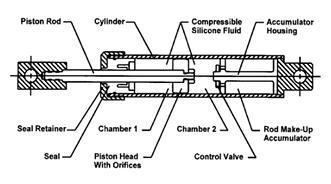
Figure 1(a): Schematic diagram of fluid viscous damper [1]
International Research Journal of Engineering and Technology (IRJET) e-ISSN: 2395-0056
Volume: 11 Issue: 06 | Jun 2024 www.irjet.net p-ISSN: 2395-0072
TheideallocationofConnectingBeams(CB)betweentwin towerstructuressusceptibletolateralloads suchaswind andearthquakes hasbeenresearchedbyPenumatchaetal. (2020).Accordingtotheanalysis,the"lateralsway"atthe topofthestructureagainstwindwasonlypermittedif all floors were connected with CB, and the "story drift" also compliedwiththecode'scriteriaonearthquakeresistance. [13] Theseismicresponse oftwo nearbyfifteen- andtenstorybuildingslinkedbyaviscousdamperwasinvestigated by Khan et al. (2020). further compares the building's reactionswhenunder-andcritically-dampeddampersare used. According to research, critically damped dampers performbetterthanunderdampeddampers.
[7] A simplified 3-DOF model of a twin-tower building connectedbyasky-bridgewascreatedbyHuang-shengetal. (2013).Itwasdemonstratedthattwomulti-storybuildings connectedbyasky-bridgeequippedwithdampersmightuse theidealconnectionparametersthatwereobtainedfromthe reduced 3-DOF model.[2] Tubaldi (2015) examined the characteristics of the dynamic behavior of two nearby structures that range in height and are joined by viscous/viscoelasticdampersthatareplacedatthetopofthe buildingthatistheshortest.Itwas demonstratedthatthe damperproperties'earlydesignensuredthebestpossible controlagainstseismicloadings. [15] YangandLam(2013) investigated the bidirectional excitations and dynamic responsesoftwobuildingslinkedbyviscoelasticdampers. Building eccentricity have an impact on the connecting dampers' efficacy for asymmetric structures. The linking viscoelasticdampershavethepotentialtosignificantlylower the maximum displacement and the maximum base shear responsesfornearbysymmetricbuildings. [16] Underbase acceleration, Patel and Jangid (2013) are examining the dynamic behavior of two symmetrically similar nearby structureslinkedbyviscousdampers.Thedynamicreactions ofnearbysimilarstructureswereshowntobelessenedby the viscous dampers during both actual and harmonic earthquakestimulation.Furthermore,aconnecteddamped system can employ the optimal damping coefficient of a damperthatwasdeterminedforalinkedundampedsystem. [12] Shanghai International Design Center's (SHIDC)
structuralcharacteristicsduringearthquakeswereassessed byZhou etal.(2016).Studieshavedemonstrated thatthe failure sequence of the structural elements was plausible and that the maximum interstory drift may meet the restrictions stipulated in the Chinese code. The natural periodsfoundinnumericalanalysisandshakingtabletests showed little differences. [17] An assessment of the coupling-control impact of a skybridge for nearby tall buildings was conducted by Lee et al. (2010). Based on numericalstudies,itwasdemonstratedthatthesky-bridge may reduce the dynamic reactions of the paired tall structures by efficiently increasing their damping ratio. It was also discovered that adding more viscous dampers mightgreatlyenhancethecoupling-controleffectoftheskybridge. [9] Mahmoudetal.(2015)investigatedtheseismic behaviorofthePetronasTwinTowersinMalaysia,whichare twoextremelytallstructuresconnectedbyaskybridge.The findings show that the total dynamic response of the connected towers in both longitudinal and transverse directionsisnotsignificantlyimpactedbythepositionofthe linking bridge. While the comparable storeys in the longitudinaldirection(x-direction)wereinsensitivetothe placementoftheconnectingbridge,theinter-story drift in the transverse direction (y-direction) demonstrated sensitivitytochangesinbridgelocation.
[10] In order to lessen earthquake-induced structural reactions,Kimetal.(2005)lookedattheimpactofplacing viscoelasticdampers(VEDs)inlocationssuchseismicjoints or building–sky-bridge connections. Reduction of earthquake-induced reactions can be achieved by using VEDsinseismicjointsorsky-bridges.Theidealdimensions of VED resulted in a decrease in both the absolute and relative displacements of linked structures, along with a reductioninhystereticenergyandplasticdeformation. [8]
Thisworkexamineslinearviscousdampersandtheshear wall system. Moreover, the building's outside has a shear wallsysteminstalled.Additionally,ashearwallsystemwith dampersattheoutsideperipherywasstudied.
Thesearethemaingoals,whicharebasedontheliterature researchthatwasdone:-
To evaluate the effectiveness of linked tall structuresequippedwithshearwalls.
To investigate how linked tall structures with passiveviscousdampersoperate.
To investigate several factors for the linked structures,suchasfoundationshear,displacement, acceleration,andstorydriftunderconsideration.
To research how linked buildings behave and functionatdifferentSkyBridgesites.
-
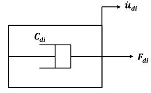
Two(25-story)buildingswith(35×35)mplandimensions have been chosen for the investigation. The Sky Bridge is
Volume: 11 Issue: 06 | Jun 2024 www.irjet.net
locatedbetweenthe(12th&13th)floorandthe(24th&25th) level. The distance between two buildings is measured in meters. Four distinct systems with shear walls serving as lateral load-resisting systems for dead load, live load, earthquakeload,andwindloadareanalyzedanddesigned usingtheETABSprogram.Analysisofwind,earthquaketime history, responsespectrum, andstaticearthquakes are all carriedout.ThewindloadiscomputedusingtheGustfactor method. Table I lists the building's attributes as well as loadinginformation.Tosimulatebeams,hot-rolledI-sections areutilized.Themodelforcolumnsandbracingslookslike pieces of a built-up box. All model section details are provided in Table III. The Sky Bridge's beam and column sizesforModel-1are(B-350X55).ForModels2-4,storeys (12&13) have beam and column sizes of (B-800X65), whereasstoreys(24&25)intheSkybridgehavebeamand columnsizesof(B-550X55)&(B-500X55),respectively.The restcomeinsizes (B-350X55).The sectional information is predicated on a rigorous design review.
Followingarethecasesconsideredinthepresentstudy:-
(A) standard frame structure with a shear wall (SW) TheSWwallelementismodeledasbeingshell-thin. (Figure-2)displaystheplan,elevation,andthreedimensional perspective of the traditional model withSW.
(B) Standard frame system exclusively in Sky Bridge withLinearViscousDamper(LVD)andSWAsseen in(Figure-3),onlyatSkyBridgearelinearviscous dampersavailable.Linkcharacteristicsareusedin themodelingofLVDs.
(C) StandardframesystemwithLVDandSWatevery story as seen in (Figure-4), LVDs are available at SkyBridgeaswellasattheouterperiphery.
(D) Standard frame structure with LVD and SW at differentstorylevelsasseenin(Figure-5),LVDsare availableattheSkyBridgeaswellasatalternative storeysaroundtheouterperiphery.
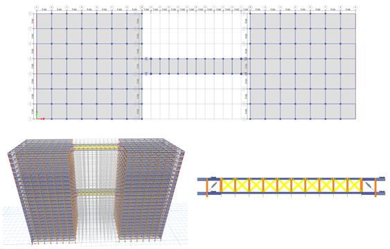
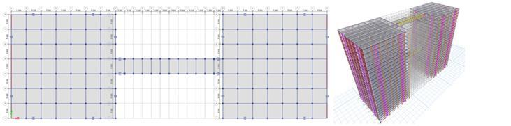
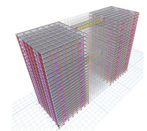
Table I: Properties and data: -
Volume: 11 Issue: 06 | Jun 2024 www.irjet.net p-ISSN: 2395-0072
Planaspectratio(Lt/Bt) 1
Gradeofsteelforsteelsection Fe250
Concretegrade(Slab) M-25
Slab(Thickness) 125mm
Table II: Details of Earthquake considered in the study:
Table III (1): Section Details: -
Model Element
Model(1)
Model(2)
Model(3)
Model(4)
Table III (2): Section Details: -
Model Element
Model(1)
Model(2)
Model(3)
Number of Storey 16-20 21-25
Beam ISWB500 +PLATE25 ISWB600-1
BeamcoSW ISWB550 2+(PE)40 ISWB450 +(PE)40
Column B-400x55 B-350X65
Model(4)
Number of storeys 1- 5 6-10 11-15
Beam ISWB550 +PLATE40 ISWB550 +PLATE40 ISWB550 +PLATE40
Beam co-SW ISWB6002+(PE)40 ISWB6002+(PE)40 ISWB6002+(PE)40
Column B-600x75 B-450X65 B-400X55
Bracing (SB) B-350X55
Beam ISWB550+ (PE)40 ISWB550+ (PE)40 ISWB550+ (PE)40
Beam co-SW ISWB6002+(PE)40 ISWB6002+(PE)40 ISWB6002+(PE)40
Column B-600X75 B-500X55 B-450X55
Bracing (SB) B-350X55
Beam ISWB550+ (PE)40 ISWB550+ (PE)40 ISWB550+ (PE)40
Beam co-SW ISWB6002+(PE)40 ISWB6002+(PE)40 ISWB6002+(PE)40
Column B-600X75 B-500X55 B-450X55
Bracing (SB) B-350X55
Beam ISWB550+ (PE)40 ISWB550+ (PE)40 ISWB550+ (PE)40
Beam co-SW ISWB6002+(PE)40 ISWB6002+(PE)40 ISWB6002+(PE)40
Column B-600X75 B-500X55 B-450X55
Bracing (SB) B-350X55 International Research Journal of Engineering and Technology (IRJET) e-ISSN: 2395-0056
Bracing (SB)
B-350X55
Beam ISWB500+ (PE)25 ISWB600-1
BeamcoSW ISWB550+ (PE)20 ISWB450+ (PE)40
Column B-400X55 B-350X45
Bracing (SB) B-350X55
Beam ISWB500+ (PE)25 ISWB600-1
BeamcoSW ISWB550+ (PE)20 ISWB450+ (PE)40
Column B-400X55 B-350X45
Bracing (SB)
B-350X55
Beam ISWB500+ (PE)25 ISWB600-1
BeamcoSW ISWB550+ (PE)20 ISWB450+ (PE)40
Column B-400X55 B-350X45
Bracing (SB)
B-350X55
3.RESULTS & DISCUSSION: -
A. Effect of Cd: -
Thedampingcoefficient'svalueisdeterminedbyoptimizing it for almost constant acceleration and displacement. (Figures:-6(a)&6(b))respectivelyillustratetheeffectofCd onthereactioncharacteristicsof(Model3&Model4)under the Imperial Valley Earthquake. The displacement and accelerationoftheupperlevelaretakenintoaccounthere.It has been noted that when the value of Cd rises, response parameters fall. Regarding (Models 3 & 4), the damping coefficient'soptimalvalueis200000kNs/m
International Research Journal of Engineering and Technology (IRJET) e-ISSN: 2395-0056
Volume: 11 Issue: 06 | Jun 2024 www.irjet.net p-ISSN: 2395-0072
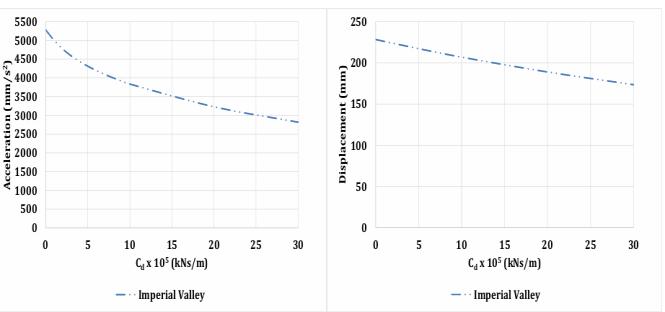
Figure 6(a): Effect Cd on various response parameters for Model-3
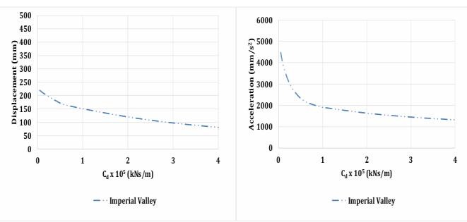
Figure 6(b): Effect Cd on various response parameters for Model-4
B. Hysteresis loop: -
Figures 7(a) and 7(b) depict the hysteresis loop for the damperatstorey-25inModels3and4,respectively,under theconditionsoftheImperialValleyEarthquake.Itcanbe seen that energy is being lost from the damper force vs. displacementloop.Thedamper'scharacteristicsareshown inthedamperforcevs.velocityhysteresisloop.
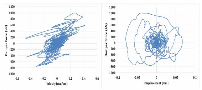
Figure 7(a): Hysteresis loop of Force v/s Displacement and Force v/s Velocity under Imperial Valley Earthquake for Model-3
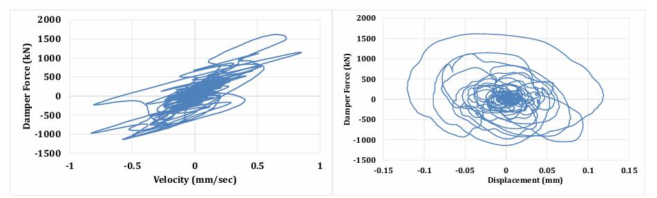
Figure 7(b): Hysteresis loop of Force v/s Displacement and Force v/s Velocity under Imperial Valley Earthquake for Model-4
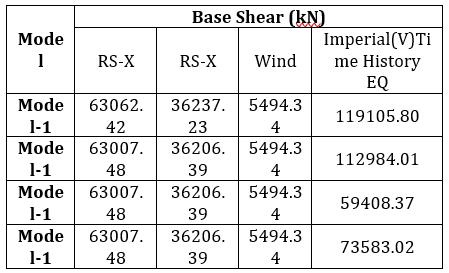
C. Base Shear: -
Base shear for each system is shown by various investigations in Figure 8 and Table IV. For model 3, the minimumbaseshearisdeterminedineachanalysis.Thereis anotabledecreaseinbaseshearinthemodelsusingLVDs. Based on the time history study, the average percentage reductioninbaseshearforModels3and4isdeterminedto be54.98%and50.13%,respectively,comparedtoModel1.
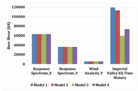
Figure 8: Comparison of Base Shear
Table IV: Base Shear of different Earthquake Time Histories: -
International Research Journal of Engineering and Technology (IRJET) e-ISSN: 2395-0056
Volume: 11 Issue: 06 | Jun 2024 www.irjet.net p-ISSN: 2395-0072
D. Max Storey Displacement: -
A comparison of the maximum storey displacement by serviceabilityloadcombinationisshowninFigure9.ASW system with LVDs at every level, Model 3, has the lowest storey displacement. The maximum storey displacement undertheImperial ValleyEQTimeHistory isdisplayed in (Figures10&11).Model3hasagreatestreductioninstorey displacement,or49.23%,whencomparedtoModel1.
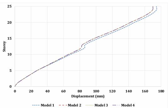
Figure 9: Maximum Displacement: -
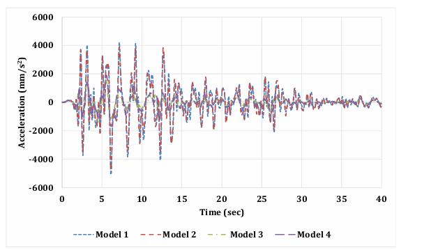
Figure 10: Displacement Response for different systems under Imperial Valley Earthquake Time History
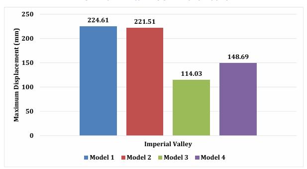
Figure 11: Max Storey Displacement based on Earthquake Time History analysis
E. Drift Ratio: -
The drift ratio for a combination of serviceability loads is showninFigure12.Formodel4intheserviceabilityload combination,theminimumdriftratioisnoted
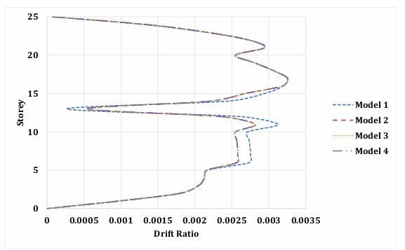
Figure 12: Drift Ratio based on Serviceability load combination
F. Time Period: -
Acomparisonofthetimesforvarioussystemsisshownin Figure13.Incomparisontoprevioussystems,Model4isa stiffer system. Since LVDs don't provide the structure any morerigidity,thereisn'tachangeinthetimeperiod.
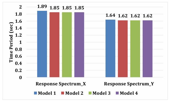
Figure 13: Comparison of Time Period
G. Acceleration: -
Figure14showstheaccelerationresponseatthetoplevelof different systems under the Imperial Valley Earthquake TimeHistory.Figure15showsthetopstorycomparisonof thegreatestaccelerationforthetimehistoryanalysisofthe ImperialValleyEarthquake.TheModel1SWsystemisstiffer than other systems because of its greater acceleration values.Ithasbeen notedthatcomparedtoothersystems, LVDsystemsacceleratemoreslowly
International Research Journal of Engineering and Technology (IRJET) e-ISSN: 2395-0056
Volume: 11 Issue: 06 | Jun 2024 www.irjet.net p-ISSN: 2395-0072
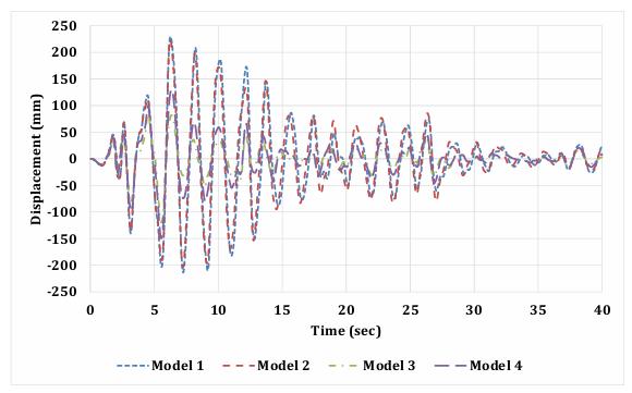
Figure 14: Acceleration Response for different systems under Imperial Valley EQ Time History
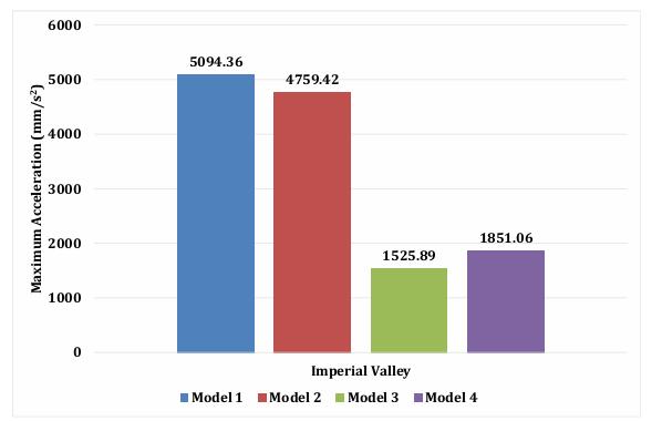
Figure. 15 Comparison of Maximum Acceleration due to Imperial Valley EQ Time History
4.CONCLUSION: -
Thisstudyexamineshowalinkedtallbuilding'sshearwall and linear viscous damper respond to wind and seismic loads.Theinvestigationconductedallowsforthefollowing keyfindingstobemade.
To improve their performance in the event of an earthquakeorwindforce,connectedtallbuildings mustincludelateralloadresistingsystems.
GivingLVDsallowsforcompetentcontroloverthe building'sdisplacementandaccelerationresponse.
The Model 3 conventional frame system SW with LVDfittedateverystorywithdampersexhibitsthe minimumdisplacement.Timehistorystudyshows that for Model 3 compared to Model 1, the maximumstoreydisplacementatthetopstoreyis reducedby50.95%.
Model 3,orthe traditional framesystemwithSW and LVD, exhibits the least acceleration over all storeys.Accordingtotimehistorystudy,Model3's
accelerationatthetopstoryis70%lessthanModel 1's.
TheModel3conventionalframesystem,whichhas both SW and LVD at every storey for response spectrumandtimehistorystudy,exhibitstheleast amount of base shear. By comparing Model 3 to Model 1, the base shear reduction in time history analysisis50.12%.
1. Feng, F. (2018). (Design and Analysis of Tall and ComplexStructures.UnitedStates:MatthewDeans)
2. Huang-sheng,S.,Mo-han,L.,&Hong-ping,Z.(2014). (Connecting parameters optimization on unsymmetricaltwin-towerstructurelinkedbyskybridge).JournalofCentralSouthUniversity,21(6), 2460–2468.
3. (IS 16700: 2017), Criteria for Structural Safety of Tall Concrete Buildings. (2017, November). New Delhi:BureauofIndianStandards.
4. (IS1893(Part 1):2016),(Criteria forEarthquake ResistantDesignofStructures.(2016,November). NewDelhi:BureauofIndianStandards)
5. (IS800:2007),GeneralConstructioninSteel-Code ofPractice.(2007,December).NewDelhi:Bureauof IndianStandards.
6. (IS875(Part3):2015),DesignLoads(Otherthan Earthquake)forBuildingsandStructures-Codeof Practice.(2015,April).NewDelhi:BureauofIndian Standards.
7. Khan, S., Kumar, C. M., & Shwetha, K. (2020). (Analytical study on the seismic behavior of two adjacentbuildingsconnectedbyviscousdampers. AIPConferenceProceedings.Bengaluru)
8. Kim, J., Ryu, J., & Chung, L. (2006). (Seismic performanceofstructuresconnectedbyviscoelastic dampers.EngineeringStructures),28(2),183-195.
9. Lee,D.G.,Kim,H.S.,&Ko,H.(2012).(Evaluationof coupling-controleffectofasky-bridgeforadjacent tallbuildings.StructuralDesignofTallandSpecial Buildings),21(5),311-328.
10. Mahmoud,S.,Abdallah,W.,Hanna,N.,&Abdelaal,A. (2016).(Seismicresponseevaluationofconnected supertallstructures.ProceedingsoftheInstitution of Civil Engineers: Structures and Buildings), 169(11),840-852.
11. Mistry, A., Mevada, S. V., & Agrawal, V. V. (2022). (Vibration Control of Tall Structureusing Various Lateral Load Resisting Systems and Dampers) InternationalJournalofCivilEngineering,9(6),2842.
12. Patel,C.,&Jangid,R.(2014).(Dynamicresponseof identicaladjacentstructuresconnectedbyviscous damper.StructuralControlandHealthMonitoring), 21(2),205-224.
International Research Journal of Engineering and Technology (IRJET) e-ISSN: 2395-0056
Volume: 11 Issue: 06 | Jun 2024 www.irjet.net p-ISSN: 2395-0072
13. Penumatcha,K.R.,Vipparthy,R.,&Yadav,A.(2020). (AStudyoneffectofConnectingBeamsina Twin Tower Structure). Journal of The Institution of Engineers(India):SeriesA,101(4),847–856.
14. Smith, B. S., & Coull, A. (1991). (Tall Building Structures: Analysis and Design. United States: A WileyIntercedencePublication).
15. Tubaldi,E.(2015).(Dynamicbehaviorofadjacent buildingsconnectedbylinearviscous/viscoelastic dampers. Structural Control and Health Monitoring),22(8),1086-1102.
16. Yang,Z.D.,&Lam,E.S.(2014).(Dynamicresponses oftwobuildingsconnectedbyviscoelasticdampers under bidirectional earthquake excitations. Earthquake Engineering and Engineering Vibration),13(1),137-150.
17. Zhou, D., Guo, C., Wu, X., & Zhang, B. (2016). (Seismic Evaluation of a Multitower Connected Building by Using Three Software Programs with ExperimentalVerification.ShockandVibration).