
International Research Journal of Engineering and Technology (IRJET) e-ISSN: 2395-0056
Volume: 11 Issue: 06 | June 2024 www.irjet.net p-ISSN: 2395-0072
International Research Journal of Engineering and Technology (IRJET) e-ISSN: 2395-0056
Volume: 11 Issue: 06 | June 2024 www.irjet.net p-ISSN: 2395-0072
Om Gadhave
1
, Mr. Manish Patil (Guide)
2
1Department of Mechanical Engineering, 2Goverment college of engineering and research Avasari (kh), 3Giant Metrewave Radio Telescope (GMRT) Khodad, (NCRA)-(TIFR).
Abstract - This research focuses on the wind analysis of a Three-meter Antenna, specifically examining the dish component. UtilizingANSYSsoftware,windtunnelsimulations were conducted to determine the drag and liftforcesactingon the antenna dish. A detailed model of the antenna dish was created using SolidWorks software. The primary objective of this analysis was to quantify the drag and lift forces under varying angles of the antenna and different wind velocities. The findings from this study provide valuable insights into the structural behavior of the antenna under wind loading conditions, aiding in its optimization and performance enhancement.
Key Words: Wind Analysis, Drag Force, Lift Force, Wind Tunnel Simulation, Three-meter Antenna dish.
1.INTRODUCTION
Wind analysis stands as a cornerstone in the realm of structural engineering, particularly concerning the design andevaluationofcriticalcomponentslikeantennadishes. Thisprojectdelvesintoacomprehensivewindanalysisofa Three-meterAntennaDish,utilizingadvancedcomputational toolssuchasANSYSFluentsoftware.Theprimaryobjective istoquantifythedragandliftforcesactingonthedishunder diversewindvelocity(20kmphto90kmph)andatdifferent positionsofdishintunnel(0degreeto90degree),crucial for ensuring its structural integrity and operational reliability.
Antennadishes,integraltocommunicationsystems,endure continuous exposure to environmental forces, with wind being a significant factor. Understanding the intricate interplaybetweenwindandantennadishesisimperativefor guaranteeing their longevity, reliability, and optimal performance.
One of the key parameters studied in wind analysis is pressuredistributionacrossthesurfaceoftheantennadish. Wind exerts pressure on the dish, creating variations in pressureacrossitssurface.Thesepressuredifferentialscan lead to localized stress concentrations, potentially compromisingthedish'sstructuralintegrity.Bymappingout pressuredistributions,engineerscanidentifycriticalareas prone to high stress and develop strategies to mitigate potentialfailuremodes.
Additionally,windanalysisinvolvesevaluatingaerodynamic forcessuchasdragandlift.Dragforce,actingparalleltothe directionofthewindflow,opposesthemotionofthedish throughtheair.Liftforce,perpendiculartothewindflow, resultsfromdifferencesinairpressureaboveandbelowthe dish'ssurface.Theseaerodynamicforcesplayapivotalrole indeterminingthedish'sstabilityandstructuralresponseto windloading.
By comprehensively studying the aerodynamic forces, engineerscananticipatepotentialstructuralvulnerabilities anddevisestrategiestomitigatethem.Furthermore,wind analysisaidsinoptimizingthedish'sdesigntoenhanceits performanceandlongevityundervaryingwindconditions. Thiscomprehensiveapproachensuresthatantennadishes notonlymeetsafetystandardsbutalsoexhibitrobustness andreliabilityintheiroperationalenvironments.
The purpose of this project is to conduct comprehensive structuraldesignandanalysisofathree-meterantennaand its accompanying dish. This antenna holds significant potentialforamultitudeofapplications,particularlyinthe realm of astronomical observations and Radio Frequency Interference (RFI) measurements. By harnessing its capabilities,wecandelveintothedepthsofspace,capturing invaluabledataforastronomicalresearch.Additionally,its precise design enables accurate RFI measurements, contributing to the mitigation of interference in radio astronomyobservations.Insummary,thisprojectseeksto develop a versatile antenna system capable of facilitating groundbreakingastronomicalobservationswhileeffectively addressingchallengesposedbyRFI,therebyadvancingour understandingoftheuniverseandenhancingtheefficiency ofradioastronomyendeavors
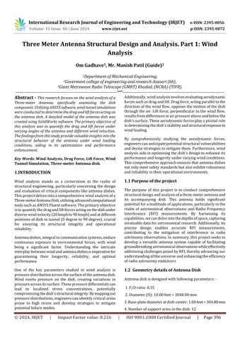
Antennadishisdesignedwithfollowingparameters:-
1.F/Dratio:0.35
2.Diameter(D):10.00feet=3048.00mm
3.Base-platediameteratdish-center:1.00feet=304.80mm
4.Numberofsupportarmsinthedish:12
International Research Journal of Engineering and Technology (IRJET) e-ISSN: 2395-0056
Volume: 11 Issue: 06 | June 2024 www.irjet.net p-ISSN: 2395-0072
5. Diameter of the shadow region at the center: 4 inch = 101.60mm
6.Widthofthesquaretubetobeusedforarms:2cm=20.00 mm
2. PHYSICAL DESCRIPTIONOF THE WIND ANALYSIS
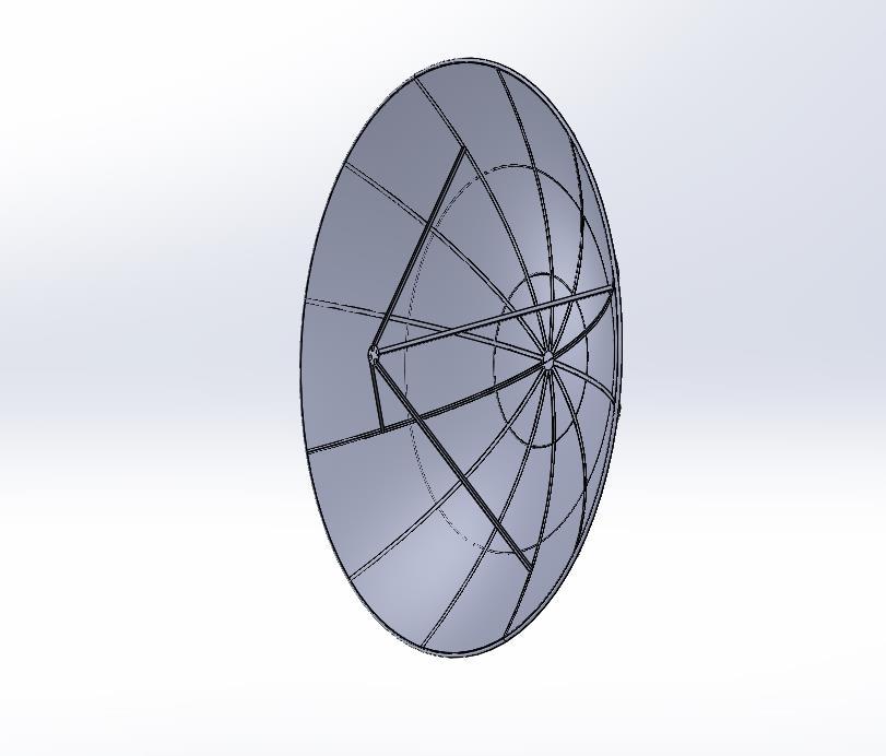
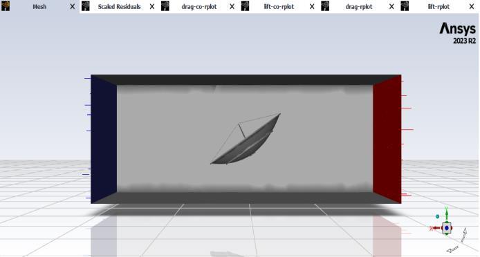
Inthewindanalysisproject,theinitialstepinvolvedcrafting a detailed model of the antenna dish using SolidWorks software.Oncethemodelwasmeticulouslydesigned,itwas saved as a .stp (STEP) file format, facilitating seamless integration into ANSYS Fluent for subsequent analysis. WithinANSYSFluent,theimporteddishmodelservedasthe focal point for the analysis, representing the physical geometryuponwhichvarioussimulationswereconducted. To replicate real-world conditions and ensure accurate results,anenclosure,akintoawindtunnel,wasmeticulously constructedaroundthedishmodelusingtechniquessuchas Boolean subtraction as shown in fig. 2. This enclosure providedthecomputationaldomainwithinwhichthewind flow interactions with the dish were examined. The enclosure, measuring 8 meters in length, served as the computationaldomainfortheanalysis,allowingforprecise examinationofwindflowinteractionswiththedish.
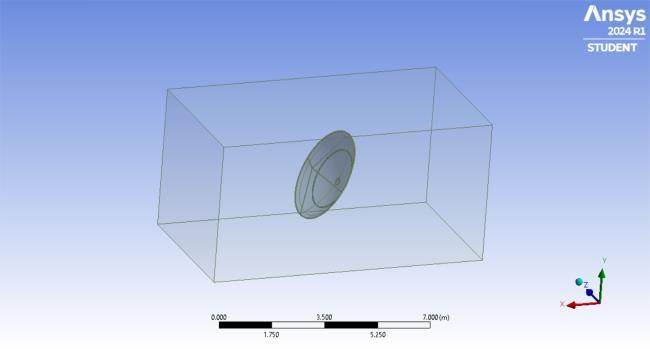
Fig-2: Enclosuresurroundingtheantennadish,providing clearviewofcomputationalsetupusedforanalysis
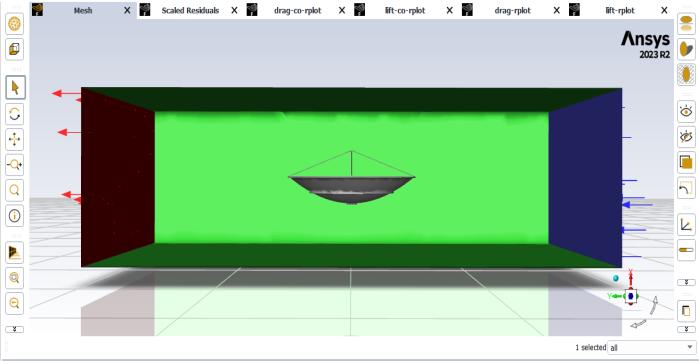
InthemeshingphaseusingANSYSFluent,defaultsettings were initially applied, followed by adjustments to the elementsizeupto100mmforimprovedaccuracy.Meshing isapivotalstepincomputationalfluiddynamics(CFD)asit subdividesthegeometryintosmallerelements,enhancing numerical calculations. Special attention was given to refiningthemesharoundcriticalareassuchastheantenna dishtocapturefinerflowdetailsandensurepreciseresults. Mesh quality parameters like aspect ratio, skewness, and orthogonality were closely monitored to guarantee the generation of a high-quality mesh conducive to robust simulations. This iterative process, aimed at balancing computationalefficiencywithsolutionaccuracy,isessential for producing reliable and meaningful results in CFDsimulations.
Followingaretheparametersofmeshassignedtoobtainthe desiredmeshcharacteristics:
i) Meshelementsize:100mm
ii) Methods:Tetrahedralmesh
iii) No.ofNodes:21798
iv) No.ofElements:108303
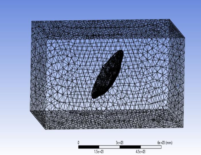
Fig-3 Showsthemeshingofmodel
International Research Journal of Engineering and Technology (IRJET) e-ISSN: 2395-0056
Volume: 11 Issue: 06 | June 2024 www.irjet.net p-ISSN: 2395-0072
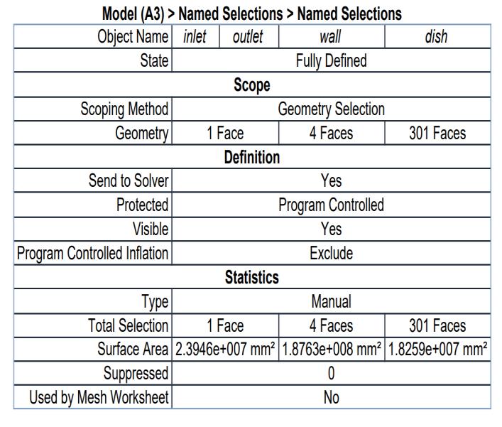
Named selections are crucial in Computational Fluid Dynamics(CFD)simulations,enablinguserstoapplyspecific boundary conditions, monitor regions of interest, and performforcecalculationswithinthecomputationaldomain. Here'swhytheyareimportant:
A) Boundary Conditions: Assign unique boundary conditions like velocity, pressure, or temperature to different parts of the geometry, especially beneficial for complexgeometries.
B) Region Monitoring: Trackandanalyzepressuredrops, heattransferrates,orflowratesinspecificareas,aidingin focusedanalysiswithinCFDsimulations.
C) Force and Moment Calculations: Essential for fluidstructureinteractionsimulations,namedselectionsdefine areasforaccurateforceandmomentcomputations,aidingin structuralanalysisandfluidforcepredictions.
Table-1 ParametersforNameselection.
2.4 Setup
InANSYSFluent,theterm"setup"referstothe configurationandspecificationofthevariousparameters andsettingsnecessarytoperformacomputationalfluid dynamics(CFD)simulation.
A) Model
The model setup inANSYS Fluentis critical foraccurately calculating wind drag and lift forces on the dish for wind analysis. Key parameters such as "Space 3D" capture the three-dimensional geometry of the dish, ensuring an accurate representation of flow behavior. "Time Steady" maintains constant flow variables over time, providing a stable simulation snapshot of the wind's impact. Additionally, the Viscous SST k-omega Turbulence Model accuratelysimulatesturbulentairflow,crucialforcapturing intricateflowpatternsthataffectdragandliftforces.These parameterscollectivelyenableacomprehensiveanalysisof
wind-dishinteraction,aidingininformeddesigndecisions andoptimizationsforenhancedperformanceandefficiency.
The solver in ANSYS Fluent performs the calculations necessarytoobtainasolutionforthespecifiedphysicsand boundaryconditions.
i) Type:Pressure-Based
ii) VelocityFormulation:Absolute
iii) Time:Constant
iv) 3Dspace
C) Boundary conditions:
In the wind analysis conducted in ANSYS Fluent, several boundaryconditionswereselectedtoaccuratelysimulate the flow behavior around the dish. These boundary conditionsplayacriticalroleindefiningtheenvironmentin whichthesimulationoperates.
1. Inlet Boundary Condition:
- Type: VelocityInlet
- Description: Theinletboundaryconditionrepresentsthe region where air enters the computational domain. By specifying a velocity inlet, a prescribed velocity profile is imposed at this boundary, simulating the incoming wind flow. Various air velocities were applied at the inlet to analyzethedish'sresponseunderdifferentwindconditions.
2. Outlet Boundary Condition:
- Type: PressureOutlet
- Description: Theoutletboundaryconditiondefinesthe regionwhereairexitsthecomputationaldomain.Bysetting itasapressureoutlet,astaticpressureisspecified,allowing the flow to exit freely without reflecting back into the domain. This condition ensures that the simulation accuratelyrepresentstheopenenvironmentsurrounding thedish.
3. Dish Surface Boundary Condition:
- Type: Wall
- Description: The dish surface boundary condition represents the solid surface of the dish. By setting it as a wallboundarycondition,theairflowisconstrainedatthis surface,simulatingtheno-slipconditionwhereairvelocity iszerorelativetothedishsurface.Thisboundarycondition isessentialforaccuratelycapturingtheinteractionbetween theairflowandthedishgeometry,enablingthecalculation ofdragandliftforces.
International Research Journal of Engineering and Technology (IRJET) e-ISSN: 2395-0056
Volume: 11 Issue: 06 | June 2024 www.irjet.net p-ISSN: 2395-0072
4. Enclosure Side Boundary Condition:
- Type: Wall
- Description: Defines the walls of the computational domain,confiningairflowtopreventartificialeffectsfrom flowescapingdomainboundaries,ensuringrealisticwind flowsimulations.
These boundary conditions collectively create a welldefined computational environment for accurately simulating wind flow around the dish, enabling precise calculations of drag and lift forces under realistic windconditions.
D) Material Properties
Material: air (fluid)
E) Solution Methods:
Inourresearch,weemphasizetheselectionofappropriate solutionmethodsinANSYSFluent,focusingonthesecondorder upwind scheme for fluid flow and heat transfer simulations.Thisschemestrikesabalancebetweenaccuracy and stability, crucial for accurately capturing wind flow behavior and computing drag and lift forces. The secondorder upwind scheme minimizes numerical diffusion, allowing faithful representation of flow features and boundary layers. However, careful mesh refinement and solution monitoring are necessary to address potential oscillationsinregionsofsteepgradients.Throughdetailed documentation of settings and parameters, our research ensures reproducibility and transparency, supporting the reliability of our findings in wind analysis and forcecalculations.
These are the Scheme selected for Variable.
• Pressure: SecondOrder
• Momentum: SecondOrderUpwind
• Turbulent Kinetic Energy: SecondOrderUpwind
• Specific Dissipation Rate: SecondOrderUpwind
In ANSYS Fluent, report definitions are essential for specifying and monitoring quantities of interest during or after a simulation. They enable tracking and recording of variousparametersandresultstoanalyzefluidfloworheat transfer behavior conveniently. For our project objectives and flow parameters, we created two report definitions: Drag and Lift coefficient. These were created under the "forcereport"optioninreportdefinitions,specifyingoutput types for drag and lift coefficients. ANSYS Fluent automaticallygeneratesthesereportsatspecifiedintervals duringthesimulation.
InwindanalysisconductedusingANSYSFluenttocalculate drag force and lift force, we employ the standard initializationmethodtosettheinitialconditionsoftheflow field. This initialization procedure is fundamental in establishing a starting point for the iterative solution process,ensuringconvergencetowardsaphysicallyrealistic solution
"Run calculation" involves executing the simulation using specifiedsettingsandparameters.Inourwindanalysiswith ANSYS Fluent for calculating wind forces, we ran the simulation for 200 iterations to achieve convergence and accuracy.Thischoicebalancescomputationalefficiencywith solution accuracy, ensuring the solution adequately converges to a steady state. We monitored convergence criteria such as residual values and solution stability throughout the simulation. Documenting our selection of 200 iterations and the monitoring process ensures transparency and reliability in our analysis, facilitating reproducibilityandunderstandingoftheobtainedresults.
3.POSITION OF DISH IN WIND TUNNEL.
International Research Journal of Engineering and Technology (IRJET) e-ISSN: 2395-0056
Volume: 11 Issue: 06 | June 2024 www.irjet.net p-ISSN: 2395-0072
In conducting the wind analysis of the dish antenna, advancedcomputationalfluiddynamics(CFD)simulations wereemployedusingANSYSFluentsoftware.Thisallowed for precise calculations of drag and lift forces within a controlled virtual wind tunnel environment. The analysis encompassed a comprehensive range of air velocities, varyingfrom20to45km/h,toaccuratelysimulatediverse wind conditions encountered in real-world scenarios. Moreover,theangularpositioningofthedishantennawithin thevirtualwindtunnelwassystematicallyadjustedfrom0 degreesto90degrees, enablinga thoroughassessment of forcedistributionacrossitssurface.Thisapproachfacilitated the examination of aerodynamic interactions between the dish's geometry and the airflow from different angles, providing valuable insights into its performance under varyingwindconditions.Thewindanalysiswasconducted separately for both the front and back sides of the dish antennausingANSYSFluent.Theresultsrevealedanotable discrepancy in the forces experienced, with the front side consistentlyexperiencinghigherwindforcescompared to thebackside.Thisobservationunderscoresthesignificance of comprehensively understanding the aerodynamic behavior of the dish antenna to optimize its performance andstructuralintegrity.Topresentthesefindingseffectively, detailed tables summarizing the calculated drag and lift forceswereincorporatedintothereport.Table6offersan overview of the forces observed during front-side wind analysis,whileTable7outlinesthecorrespondingdatafor the back side of the dish antenna. By leveraging ANSYS Fluent for simulation and analysis, the report provides valuableinsightsintotheaerodynamicbehaviorofthedish antennaundervaryingwindconditions,facilitatinginformed decision-making for design optimizations and operational enhancements
Table-2 Displaysfindingsfromwindanalysisonthedish antenna'sbacksideairflow.
International Research Journal of Engineering and Technology (IRJET) e-ISSN: 2395-0056
Volume: 11 Issue: 06 | June 2024 www.irjet.net
Table-3 Displaysfindingsfromwindanalysisonthedish antenna'sbacksideairflow.
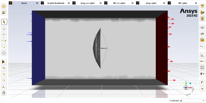
Fromthetableabove,it'sevidentthatthemaximumforceis exertedwhenthewindflowsdirectlyforwardat0degrees. Therefore, to determine the maximum force, we need to calculatethewindforceathighvelocitywhentheangleof incidenceis0degrees.
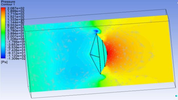
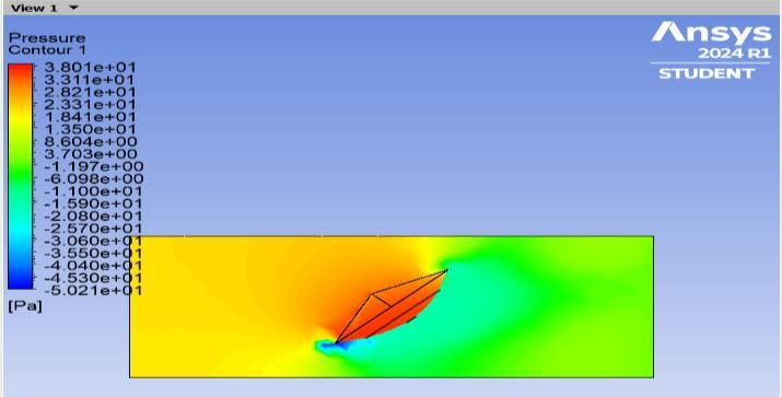
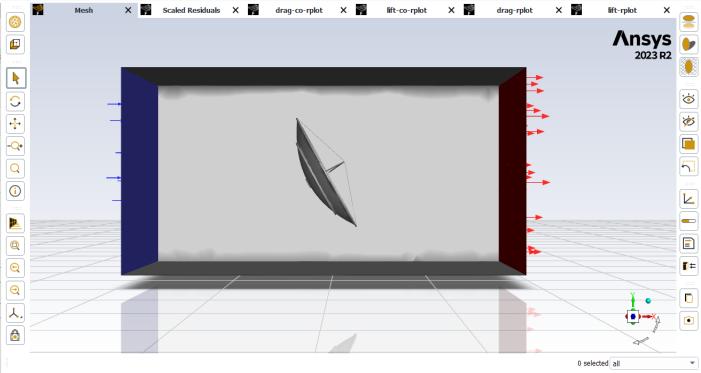
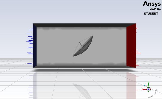
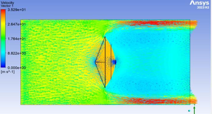
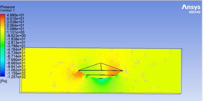
Inthewindanalysisofthedishantenna,detailedcontours were generated using ANSYS Fluent to visualize the distribution of wind forces exerted on the dish within the wind tunnel. These contours provide a comprehensive depictionofhowtheairflowinteractswiththesurfaceofthe dish,highlightingregionsofhighandlowpressure,aswellas areasofincreaseddragandlift.Byanalyzingthesecontours, valuableinsightsweregainedintotheaerodynamicbehavior ofthedishantenna,aidingintheassessmentofitsstructural integrityandperformanceundervaryingwindconditions. The figures below depict contour plots illustrating the variationinwindforcedistributionacrossthedishantenna atdifferentangularpositionswithinthewindtunnel.
International Research Journal of Engineering and Technology (IRJET) e-ISSN: 2395-0056
Volume: 11 Issue: 06 | June 2024 www.irjet.net p-ISSN: 2395-0072
ThewindanalysisconductedontheThreeMeterAntenna dish using advanced computational fluid dynamics simulationsprovidedvaluableinsightsintotheaerodynamic behavior of the structure. By systematically varying wind speeds and dish positioning from 0 to 90 degrees, it was observed that the maximum wind forces act on the dish when positioned at 0 degrees, while the forces are minimizedat90degrees.Thisindicatesthatthestructural integrityofthedishismostvulnerabletofailureunderhigh wind forces, especially when positioned at 0 degrees. Conversely, positioning the dish at 90 degrees results in reducedforces,enhancingitsstabilityandresilienceagainst windloads.
Furthermore,theanalysisrevealedsignificantdifferencesin windforcesexperiencedbythefrontandbacksidesofthe dish, emphasizing the importance of understanding aerodynamicinteractionsforoptimizingstructuralintegrity. The contour plots generated from the analysis provided visualrepresentationsofpressuredistributiononthedish, highlightingareasofmaximumandminimumpressure.This comprehensive assessment of pressure distribution and force dynamics provides a thorough understanding of the dish'sperformanceunderdiversewindconditions,essential for ensuring its reliability and functionality in real-world scenarios.
Overall,thewindanalysisconductedthroughcomputational fluiddynamicssimulationsusingANSYSFluentsoftwarehas contributedvaluableinsightsintotheaerodynamicbehavior oftheThreeMeterAntennadish,sheddinglightoncritical factorsinfluencingitsstructuralintegrityandperformance invaryingwindconditions.
Inthesecondpartstaticanalysiswill preformonthedish frametocheckthefailurepointofdish.Atwhichwindspeed the dish frame will fail can be determined by comparing resultsofwindandstaticanalysis.
[1] https://youtu.be/W1eTcXMSfuk?si=No2dkj_g0UOeKGXs
[2] AnsysWorkbenchProductreleasenotebyANSYS,Inc. Southpointe275technologydriveCanonsburg,245-256.
[3] ANSYSMeshingUser'sGuidebyANSYS,Inc.Southpointe 275technologydriveCanonsburg,120-132
[4] PatriciaMartín,Experimentalstudyoftheeffectsofdish antennas on the wind loading of telecommunication towers, Journal of Wind Engineering and Industrial Aerodynamics,Elsevier,pp.41-47,2015.
[5] CelioF.CarrilJr.,Experimentalstudyofthewindforces on rectangular latticed communication towers with antennas,Elsevier,pp.1007-1022,2003.
[6] J.D.Holmesa,R.W.BanksaandG.Robertsb,Dragand aerodynamicinterferenceonmicrowavedishantennas andtheirsupportingtowers,pp.263-270,1993.