
International Research Journal of Engineering and Technology (IRJET) e-ISSN: 2395-0056
Volume: 11 Issue: 06 | Jun 2024 www.irjet.net p-ISSN: 2395-0072
International Research Journal of Engineering and Technology (IRJET) e-ISSN: 2395-0056
Volume: 11 Issue: 06 | Jun 2024 www.irjet.net p-ISSN: 2395-0072
Swati Soni1 , Miss Preeti Sahu2 , Dr. Durga Sharma3
1Department of Electrical Engineering, Dr. CVRU Kota Bilaspur Chhattisgarh, India
2Asst. Professor, Dept. of Electrical Engineering, Dr. CVRU Kota Bilaspur Chhattisgarh, India
3 Asst. Professor, Dept. of Electrical Engineering, Dr. CVRU Kota Bilaspur Chhattisgarh, India
Abstract - Recent advancements in magnetic materials and power electronics, coupled with the availability of inexpensive,powerfulprocessors,haveledtoasignificant increase in the use of brushless direct current (BLDC) motorsacrossvariousapplications.Theseapplicationsrange from household appliances to the automotive, aerospace, andmedicalindustries.ThewidespreadadoptionofBLDC motors is attributed to their numerous advantages over othermotortypes,includinghighefficiency,rapiddynamic response, extended operational lifespan, relatively quiet operation,andbroaderspeedranges.Duetotheincreasing deploymentofBLDCmotorsinmanyreal-worldapplications inplaceoftraditionalmotors,itisessentialtoexploreand specifytheircontrolmethodsindetail.Thispaperexamines several speed and current control techniques for BLDC motors. These methods include hysteresis band control, variableDC-linkvoltage,andpulsewidthmodulation(PWM) controlstrategies.Eachofthesecontrolstrategiesinvolves proportional-integral-derivative (PID) gains, which are optimized using the particle swarm optimization (PSO) algorithm. By employing fast Fourier transform (FFT) analysis,theregulatorbehaviorisstudiedthroughfrequency analysisoftheoutputsignals,andtotalharmonicdistortion (THD) is calculated. This analysis helps in identifying the mosteffectivecontrolstrategyforBLDCmotors.
Key Words: Speed Control, BLDC Motor, Closed Loop, Review.
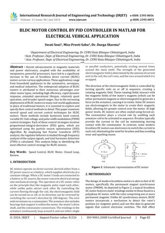
DCmotorsoperateondirectcurrent,derivedeitherfroma DCpowersourceorabattery,whichsupplieselectricityata constantvoltage.WhenaDCmotor'sleadsareconnectedto abatteryorDCsource,themotorconvertselectricalenergy intomechanicalenergy.TheoperationofaDCmotorrelies ontheprinciplethatlikemagnetic polesrepel eachother, while unlike poles attract each other By controlling the currentflowingthroughthecoil,theelectromagneticfield canbeturnedonoroff,oritsdirectioncanbereversedby switchingthecurrent'sdirectionby180degrees.Thewire endsterminateonacommutator.Thearmaturealsoincludes bearingsthatsupportitwithinthemotor,themotor'sdrive shaft,andthecommutatorconnections.Thewindingsinthe armaturecontinuouslylooparounditanduseeithersingle
or parallel conductors, potentially circling several times around the stack teeth. The strength of the generated electromagneticfieldisdeterminedbytheamountofcurrent senttothecoil,thecoil'ssize,andthecorearoundwhichitis wrapped.
Thedirectionoftheelectromagneticfieldsiscontrolledby turning specific coils on or off in sequence, creating a rotatingmagneticfield. Theserotating fieldsinteract with the magnetic fields of the stator's magnets (which can be eitherpermanentmagnetsorelectromagnets)togeneratea forceonthearmature,causingittorotate.SomeDCmotors use electromagnets in the stator to create their magnetic fields,allowingforgreatercontroloverthemotor.Athigh powerlevels,DCmotorsareoftencooledusingforcedair. The commutator plays a crucial role by enabling each armaturecoiltobeactivatedinsequence.Brushestypically provide the current to the coil by maintaining moving contact with the commutator. In contrast, some modern brushlessDCmotorsuseelectronicstoswitchthecurrentto eachcoil,eliminatingtheneedforbrushesandthusavoiding wearandsparkingissues.
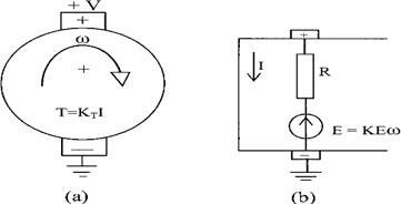
ThedesignofmodernbrushlessmotorsisakintothatofAC motors, specifically the permanent magnet synchronous motor(PMSM).AsdepictedinFigure2,atypicalbrushless DCmotorfeaturesstatorwindingssimilartothosefoundina polyphaseACmotor,withtherotorcomprisingoneormore permanentmagnets.UnlikeACsynchronousmotors,BLDC motors incorporate a mechanism to detect the rotor's position(ormagneticpoles)andusethisdatatogenerate signals that control electronic switches. The Hall effect
International Research Journal of Engineering and Technology (IRJET) e-ISSN: 2395-0056
Volume: 11 Issue: 06 | Jun 2024 www.irjet.net p-ISSN: 2395-0072
sensor is the most commonly used position/pole sensor, thoughsomemotorsemployopticalsensors.
Mathematical model of BLDC motor:
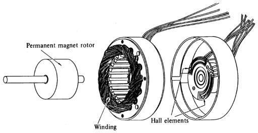
In a similar approach, BLDC motor modeling can be represented as a synchronous machine with three-phase windings. A BLDC motor, a type of multi-phase motor, is poweredbyathree-phasevoltagesource,asshowninFigure 3.Thepeakvoltageshouldremainwithinaspecificrange, neither falling below the back-EMF induced voltage nor exceedingthemotor'smaximumvoltagelimit.
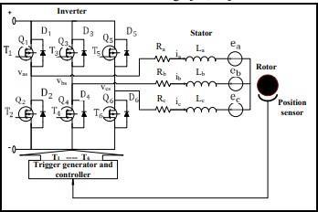
Figure 3: Three-phaseBLDCmotorequivalentcircuit
Thematrixrepresentationofthephasevoltageequationsfor theBLDCmotorcanbederivedusingKirchhoff'svoltagelaw asfollows:
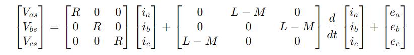
Where,
Vas,VbsandVcsrepresentthestatorvoltages.
R denotes the phase stator resistance, which remains constantacrossallwindings. ia,ibandicarethestatorphasecurrents. ea,ebandecrepresenttheback-EMFphasevoltages.
Through subtraction calculations of the phase voltage equations,thelinevoltageequationcanbederivedas:
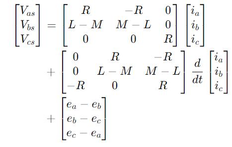
Thisequationrepresentsalinearcombinationoftheother twovoltage equations. Tosimplifythesubsequentsystem model construction, only two equations are required. By utilizingthefollowingbalancingrelationship,oneequation canbediscarded,andonevariablecanbeomitted.
ia + ib + ic = 0
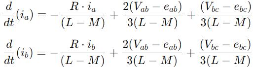
The equations can be modified using the previously mentionedequationsasfollows:
TherotorlocationisassociatedwiththetrapezoidalbackEMFs.Eachphasehasa120°phaseshift,thustheequation foreachphasecanbeexpressedas:
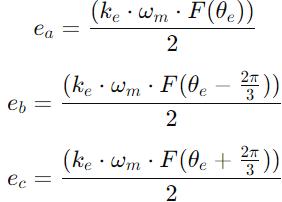
keistheback-emfconstant wmistherotorspeedand ɵeiselectricalrotoranglewhichisequalto
ɵe=(p*ɵm)/2
Where,
pisthenumberofpolesand ɵmisthemechanicalrotorangle
θm=∫wmtdt
Derived from Newton's second law and similar to the DC motor,theanalysisofBLDCmotorpowerandtorquecanbe approached from an energy transfer perspective. The transmission of power to the rotor through the air-gap, where torque is exerted, is commonly referred to as electromagneticpower.
International Research Journal of Engineering and Technology (IRJET) e-ISSN: 2395-0056
Volume: 11 Issue: 06 | Jun 2024 www.irjet.net p-ISSN: 2395-0072
pe=ea*ia+eb*ib+ec*ic
Theentiretyoftheelectromagneticpowerisconvertedinto kinetic energy after accounting for stray and mechanicallosses,thus
pe=Te*wm
Where Te is the electromagnetic torque, so that from equationstheelectromagnetictorquecanbeextractedas Te=kt/2[F(ɵe)ia+F(ɵe 2π/3)ib+F(ɵe+2π/3)ic]
Themotionequationaccountas
Te TL= J*dwm/dt+kf*wm
Where
TListheloadtorque, ktisthetorqueconstant, kfistheviscousfrictionconstantand, Jistherotormomentofinertia
Closed Loop Control Closed Loop control of BLDC motor:
Oneoftheconventionalmethodsforclosed-loopcontrolof BLDCsinvolvesutilizingeithercurrentandspeedfeedback, solely speed feedback, or no feedback for both currentandspeed.
Speed feedback
Speed feedback is obtained by measuring the voltage and current(VI)attheBLDCmotor'sterminalsintheprovided model.Thisestimatedspeedisthenfedbacknegativelyto assessanydeviationfromthedesiredspeed.Thehallsensor output is utilized for synchronization and pulse width modulation (PWM) control. A proportional-integral (PI) controller processes the error signal and utilizes it to generate PWM signals. This control approach is advantageousduetothesimplicityofVImeasurementatthe motor'soutputterminals.
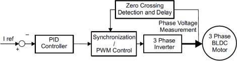
1. No speed/ current feedback:
In the block diagram presented, the alternative control strategyoperateswithoutspeedorcurrentfeedback.Here, thefocusisonestablishingaclosedloopforcurrentcontrol. In this setup, a PID controller receives only a reference currentasinput.VImeasurementisconductedoncemoreat theBLDCmotor'sterminals.Themeasuredcurrentisthen compared with the desired reference, and based on this comparison, gate pulses for the inverter are generated to regulatethecurrentflow.
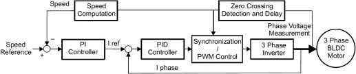
2. Speed and current feedback:
Thisapproachtoclosed-loopspeedcontrolforBLDCmotors incorporatessimilarfeedbackmechanismsastheprevious technique. However, feedback is integrated into various componentsalongthecontrolpath.Initially,theactualspeed iscomparedwiththedesiredreferencespeed.Subsequently, aPIcontrollerprocessestheresultingerror,leadingtothe computation of a reference current. This current is then comparedwiththecurrentmeasuredattheoutputterminal before being further adjusted by passing it through a PID controller. This method necessitates two stages of tuning and additional circuitry, making it the most intricate technique.Followingthis,thePWMcontrolunit,responsible for generating logic pulses for PWM control, receives the outputofthePIDcontroller.
International Research Journal of Engineering and Technology (IRJET) e-ISSN: 2395-0056
Volume: 11 Issue: 06 | Jun 2024 www.irjet.net p-ISSN: 2395-0072
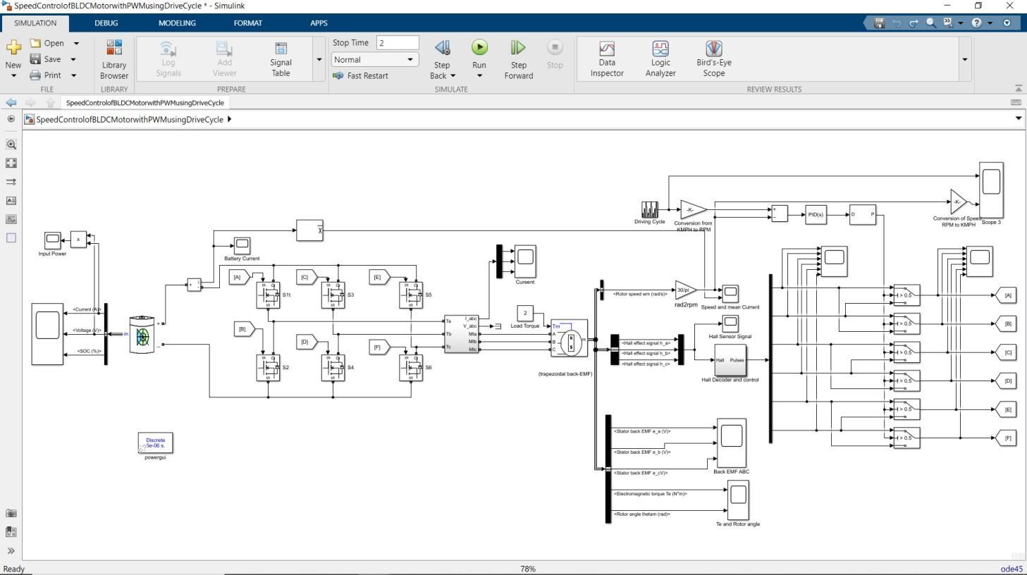
3. MATLAB/SIMULINK
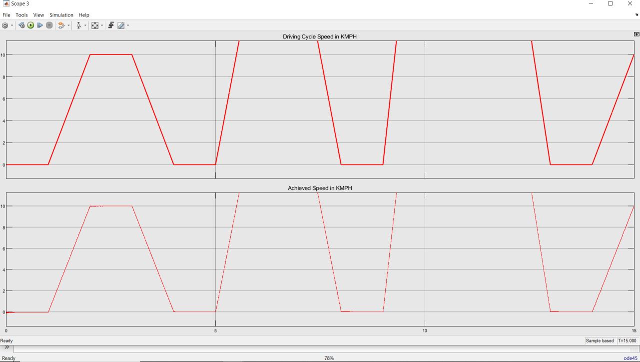
4. RESULTS
International Research Journal of Engineering and Technology (IRJET) e-ISSN: 2395-0056
Volume: 11 Issue: 06 | Jun 2024 www.irjet.net p-ISSN: 2395-0072
BLDC motors offer numerous advantages compared to brushed DC and induction motors, making them highly desirableacrossvariousapplications.Onekeyadvantageis theirsuperiorspeedversustorquecharacteristics,enabling precise control over motor operation. This feature is particularlyvaluableinapplicationsrequiringrapiddynamic responsiveness, where BLDC motors excel. Additionally, BLDC motors boast greater efficiency and dependability, resulting in reduced energy consumption and enhanced reliability. These factors contribute to longer operational lifespans,makingBLDCmotorsacost-effectivechoiceover their counterparts. Moreover, BLDC motors operate more quietlythantraditionalmotors,reducingnoisepollutionin various settings. They also offer broader speed ranges, allowing for versatile performance across different operationalrequirements.Anothersignificantbenefitisthe reductioninarcing,whichenhancessafetyandprolongsthe motor'slifespan.Additionally,BLDCmotorsexhibitahigher delivered torque-to-size ratio, maximizing output in constrainedspaces.
TheseadvantagesrenderBLDCmotorsparticularlybeneficial in applications where space and time constraints are prevalent. In aerospace applications, where weight is a critical consideration, BLDC motors offer a compelling solutionduetotheirlightweightconstructionandefficient operation. Their ability to deliver high torque in compact sizes makes them ideal for powering various aerospace systems, ranging from actuators to propulsion systems. Various studies have examined and evaluated the performance of BLDC motors under different conditions. These outcomes have been meticulously documented and analyzed within the context of BLDC motor applications. Throughrigoroustestingandexperimentation,researchers have gained insights into optimizing BLDC motor performance,addressingspecificchallenges,andexpanding theirrangeofapplications.
1.BasimAlsayid,WaelA.Salah,YazeedAlawneh."Modelling of sensored speed control of BLDC motor using MATLAB/SIMULINK."InternationalJournalofElectricaland ComputerEngineering(IJECE),Volume9,Number5,October 2019.
2. Hayder Salim Hameed. "Brushless DC Motor Controller DesignUsingMatlabApplications."20181stInternational ScientificConferenceofEngineeringSciences-3rdScientific ConferenceofEngineeringScience(ISCES).
3. K. Sarojini Devi, M. Dhanasekaran, S. Muthulakshmi. "ImprovementofSpeedControlPerformanceinBLDCMotor UsingFuzzyPIDController."2016InternationalConference on Advanced Communication Control and Computing Technologies(ICACCCT).
4. Ling Xu, Jian-Guo Song, Qiang-Qiang Lin. "Brushless DC Motor Speed Control System Simulink Simulation." 2016 IEEE International Conference on Power and Renewable Energy.
5.MdMustafaKamal,Dr.(Mrs.)LiniMathew,Dr.S.Chatterji. "Speed Control of Brushless DC Motor Using Fuzzy Based Controllers."2014IEEEStudents’ConferenceonElectrical, ElectronicsandComputerScience.
6.MSandeep,BLachulal."Design of AClosed Loop Speed ControlForBLDCMotor."InternationalRefereedJournalof Engineering and Science (IRJES), Volume 3, Issue 11, November2014.
7. Maloth Purnalal, Sunil Kumar T K. "Development of Mathematical Model and Speed Control of BLDC Motor." InternationalJournalofElectricalandElectronicsEngineers (IJEEE),Volume07,Issue01,Jan-June2015
8.RushabhkumarS.Patil,ChetanM.Bobade."SpeedControl ofPermanentMagnetBrushlessDCMotorwithParameter Optimization."InternationalResearchJournalofEngineering andTechnology(IRJET),Volume07,Issue06,June2020.
9. V M Varatharaju, B L Mathur, K Udhyakumar. "Speed Control of PMBLDC Motor Using MATLAB/Simulink and Effects of Load and Inertia Changes." 2010 International ConferenceonMechanicalandElectricalTechnology(ICMET 2010).
10.Y.NarendraKumar,P.EswaraRao,P.VijayVarma,V.V. Ram Vikas, P. Kasi Naidu. "Speed Control of BLDC Motor Drive By Using PID Controllers." International Journal of Engineering Research and Applications, Vol. 4, Issue4,April2014.