
International Research Journal of Engineering and Technology (IRJET) e-ISSN: 2395-0056
Volume: 11 Issue: 06 | Jun 2024 www.irjet.net p-ISSN: 2395-0072
International Research Journal of Engineering and Technology (IRJET) e-ISSN: 2395-0056
Volume: 11 Issue: 06 | Jun 2024 www.irjet.net p-ISSN: 2395-0072
Krishna Kumar1, Dr. Amit Agrawal 2, Preeti Sahu3
1Department of Electrical Engineering, Dr. CVRU Kota Bilaspur Chhattisgarh, India
2Asst. Professor, Dept. of Electrical Engineering, Dr. CVRU Kota, Bilaspur, Chhattisgarh, India
3 Asst. Professor, Dept. of Electrical Engineering, Dr. CVRU Kota, Bilaspur, Chhattisgarh, India
Abstract - A 3-phase grid-connected PV system with an inductionmotorrunningatdifferentloadsispresentedhere. The system employs the Perturb and Observe algorithm for MPPT (Maximum PowerPoint Tracking) to ensure precise and responsive performance. A D.C-D.C boost converter is employed to increase the low D.C voltage from the photovoltaic system. The Dq control strategy combined with the sinusoidal pulse width modulation strategy is utilized as a voltage control method. An inverter and photovoltaic array are linked via a bidirectional power flow. The output of the inverter uses a lower pass filter to filter out higherfrequency ripples. A PLL (Phase Locked Loop) feedback control method is employed for inverter voltage synchronization with the grid voltage, generating the necessary reference signal. Additionally, a simulation model is created to analyze the performance of a 3-phase induction motor, examining rotor and stator currents, rotor speed, and electromagnetic torque under various load conditions
Key Words: PV System, MPPT, Grid, phase locked loop, bidirectionalinverter
Introduction
Due to the rising demand for energy and the depleting availability of non-renewable resources, theproduction of power from these sources is hampered by a number of problems, including water loss and environmental problems including the greenhouse effect and global warming.Oneofthebestsourcesofenergyissolarenergy. Inthiswork,a3-phasePVsystemthatiswiredtothegrid is constructed as well as simulated using MATLAB Simulink. The precision and responsiveness of the photovoltaic system are evaluated by utilizing the MPPT approach, which makes use of the Perturb along with the Observealgorithm.
The solar system in question is composed of 60 cells per module and 1300 parallel strings connected inseries. A5 KW3-phaseloadcanbepoweredbyeachpanel's213.15W power output.The low D.C voltage of a photovoltaic (PV) systemisincreasedtothehigherD.Cvoltage necessaryfor grid synchronization using an example of a D.C-D.C boost converter. Everyelementof the provided system has been developed, reviewed, and tested. An inverter and
photovoltaic array are linked via a bidirectional power flow. The inverter output uses a lower pass filter to filter out higher-frequencyripples. Since the PLL (PhaseLocked Loop) feedback control method produces the necessary reference signal, it is utilized to synchronize the inverter voltage with the grid voltage. The simulation model includes a sinusoidal PWM (Pulse Width Modulation) methodanda3-phasegridassociatedwithavoltagesource inverter. The speed of the rotor, stator current, electromagnetic torque,androtorandstatorcurrentofan induction motor operating under various load circumstances have been analyzed. Electromechanical energy converters like 3-phase induction motors convert 3-phaseelectricalinputpowerintomechanicalpower.
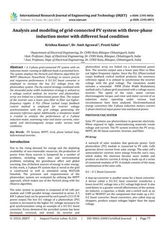
Solar PV systems use photovoltaics to generate electricity. When exposed to light, semiconducting materials create voltage and current. The PVsystem involves the PV array, MPPT,DC-DCboostconverter,Inverter,andFilter.
A network of solar modules that generate power. Each photovoltaic (PV) module is connected to PV cells. Cells generate direct current from solar energy. Thesolar cell's semiconductor receives more energy fromthe sun's rays, which makes the electrons become more mobile and produceanelectric current.A string is madeup of a series ofconnectedmodulesofPV.Amoduleconsistsofthemany combinationsofthesolarcells.
Astep-upconverterisanothernameforaboostconverter. A device called a D.C-D.C boot converter transforms a lower-levelD.CvoltageintoaD.Cvoltagehigh-level.Italso contributestoagreateroveralleffectivenessofthesystem. An inductor, a capacitor, a diode, and a switch such as an IGBT or MOSFET are the components that make up a D.CD.C boost converter. Boost converters, also called step-up choppers, produce output voltages higher than the input voltage.
International Research Journal of Engineering and Technology (IRJET) e-ISSN: 2395-0056
Volume: 11 Issue: 06 | Jun 2024 www.irjet.net p-ISSN: 2395-0072
MPPT algorithmwhichextractsmaximumpowerfromthe PV module under specified conditions. The maximum power point is the PV module's maximum power output voltage. Maximum power depends on sun radiation and temperature. MPPT maximizes PV module power by operatingthematthehighestefficientvoltage.
Inverters transform power from D.C. to A.C.at the desired voltage and frequency. Inverters are static. It converts electrical power. However, it cannot create electricity. Inverters come in three types: modified sine wave, square wave, and sine wave. Inverters are crucial to solar energy systems. It transforms solar panel-generated DC power to grid-usedACelectricity.
Acircuitthathastheabilitytopasssomefrequencieswhile attenuating others is called a filter. Without a filter, the currentproducedbythegrid-connectedinverterhasahigh harmonic content, which affects the grid voltage and results in poor power quality. Hence the filters are used. ThePWM squarewavecannotbefedtothegrid therefore lowerpassfilter isusedto convertthissquarewaveintoa puresinewave.
Inductionmotorsareelectromechanicalenergyconversion devices which convert 3-phase electrical power input into the mechanical power output. 3-phase induction motors are used to convert such power. The components that makeupathree-phaseinductionmotorareastatoraswell as a rotor. In the rotor, there is a winding that is shortcircuited and is referred to as the rotor winding. On the otherhand,thestatorhasawindingthatisthree-phase.In ordertoprovidepowertothestatorwinding,threephases of electricity are utilized. The rotor winding is able to acquire its voltage as well as power from the stator winding and this is accomplished by electromagnetic induction.Aninductionmotor,whichismoreoftenknown asanasynchronousmotor,itisatypeofACelectricmotor which is frequently employed An induction motor generates torque by electromagnetically inducing electric current in the rotor using the stator winding's revolving magnetic field. Induction motors employ winding-type or squirrel-cagerotors.Duetotheirreducedspeed,induction motorsarecalled"asynchronousmotors."
The grid is a system of transmission lines or cables that connects different power plants to our residences and businesses.Itprovidesthedistributionunitwithelectricity
fromtheproducingunit.Fromtheproducingstationtothe load center, a significant quantity of electricity is transferred at 220 kV or higher. The super grid is the network created by these high-voltage wires. Operating at 132kVorbelow,thesub-transmissionnetworkreceivesits feedfromthesupergrid.Becausethefuelsourceiscloseto the grid's power plant, the system's transportation costs are reduced. However, it's positioned distant from any major population centers. The step-down transformer at the substation helps to reduce the high-voltage electricity generatedbeforeitissenttothecustomers.
Matlab software is used to stimulate grid grid-connected PV systems with three three-phase induction motors. To makeupthesystemphotovoltaicarray,filter,bidirectional inverter, boost converter, MPPT controller, inverter controller,grid,andinductionmotorareusedherePVgridconnectedsystemusingVSI(VoltageSourceInverter)with a sinusoidal pulse width modulation technique has been developed. To get accurate and fast response MPPT algorithm and Perturb and Observe algorithm are used in this PV system. No batteries are employed here so energy losses across the battery are zero boost converter is utilizedheretoStepupthePVvoltagegeneratedvoltageas wellasfedonabidirectionalinverterherevoltageofDCis converted into AC voltage by utilizing an inverter controllerafterconversionofdctoacripplearetherethat are removed by using filter circuit here three phase inductionmotorareconnected.


Figure.Gridblockschematicforthelinkedphotovoltaic system
Solar technology with semiconductors, and PV technology transforms sunlight or sun rays into direct current or electricity. The solar cell's semiconductor receives more energy from the sun's rays, which makes the electrons become more mobile and produce an electric current. PV cellsare oftenmountedonaframeknownasamoduleand wired to one another. A large number of modules are combined to create an array. The number of modules can be raised or lowered depending on how much power is needed. Different semiconductor materials can be used to create PV cells. Although silicon is the most popular
International Research Journal of Engineering and Technology (IRJET) e-ISSN: 2395-0056
material, other materials can also be used to enhance the effectivenessofturningsunlightintopower.
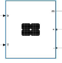
MPP(MaximumPowerPoint)Voltage=29ThePVarrayis madeupof1300parallelstrings.Eachstringismadeupof 11modulesand the moduleismadeupof60cells.
The variable irradiance is assessed by the Perturb and Observe method. As seen in Figure 3.3, the tested circumstances are examined at a constant temperature of 25°C and under three distinct irradiances: high (1000W/m2),medium(500W/m2),andlow(100W/m2).It can be observed from Figure 3.3 that the PV module's Maximum PowerPoint changes with irradiation. At constant temperature, a greater value of maximum power is correlated with higher irradiance. Additionally, it is noted that each irradiance has a single peak power point. The local maximum power point is the name given to this peak(LMPP).
The Perturb and Observe algorithm is evaluated under variableirradiance.
D.C-D.Cbootconverterisadevicethattransformsalowerlevel D.C voltage into a higher-level D.Cvoltage. A step-up converter is another name for a boost converter. It also contributestoagreateroveralleffectivenessofthesystem. An inductor, a capacitor, a diode, and a switch such as an IGBTorMOSFETarethecomponentsthatmakeupaD.C-D.C boost converter. The output pulse signalfrom the MPPT controller controls the switch. At the moment of switch activation, the diode is reverse-biased, hence the output currentandinductorcurrentwillbeequal.Thevoltagethat isplacedacrossthecapacitorduringtheONintervalisthe
outputvoltage.Thecapacitormustbeofsufficientvalueto maintain the voltage. The diode becomes forward-biased while the inductor is active bydischarging in the opposite direction from the off interval. The voltage across the inductor servesas a measure of the voltage differential among the input & output. The output signal from the MPPT block controls the switch to extract maximum power. The signal generatedby the MPPT block generates thesignalwhichispassedthroughthePWMgenerator.The duty cycle produced by the MPPT Controller is compared with the sawtooth waveform or triangular waveform that will generate the signal which will control the IGBT of the boost converter to extract maximum power from the PV array.
A control loop feedback device controls all process variables in this controller. A system can be directed towardatargetlocationorlevel usingthiskindofcontrol. It controls temperature practically everywhere and is utilized in several chemical reactions, automation, and scientific operations. In order to preserve the genuine outputfromatechnique,suchasbeingnearthetarget,this controller uses closed-loopfeedback;ifthisisnotfeasible, itwilloutputatthefixedpoint.
This controller uses a control loop feedback device to regulate each process variable. A system can be held at a constant level or guided toward a desired point with this type of control. It is utilized virtually universally for controlling temperature and in many chemical reactions, automation, and scientific operations. In this controller, closed-loopfeedback isusedtomaintaintheactual output fromanapproach like closetotheobjectiveintheevent thatoutputatthefixedpointisnotfeasible.
The voltage control method has been utilized to keep the DC voltage at the inverter's input constant. The control loop controls switch on/off timings via inverter gate signals. The control loop outputs regulated PWM that regulates the inverter's IGBT switch switching. The inverter produces three-phase sinusoidal voltages and currents.
The current produced by the grid-connected inverter comprises a lot of harmonics without the filter, when this current is flowed through the grid it causes power quality issues by the grid voltage. Hence the filters are used. The PWM square wave cannot be fed to the grid therefore lower pass filter is used to convert this square wave to a puresinewave
ThePVArrayisgiventwoinputs.Firstisirradiationwhich is variable, 1000 W/m2 (Maximum) and 100 W/m2 (Minimum). Second is temperature which is keptconstant at 25⁰C. The MPPT method P & O algorithm is used. The variousresultswhichareobtainedareshownbelow.
Volume: 11 Issue: 06 | Jun 2024 www.irjet.net p-ISSN: 2395-0072 © 2024, IRJET | Impact Factor value: 8.226 | ISO 9001:2008
International Research Journal of Engineering and Technology (IRJET) e-ISSN: 2395-0056
Volume: 11 Issue: 06 | Jun 2024 www.irjet.net p-ISSN: 2395-0072
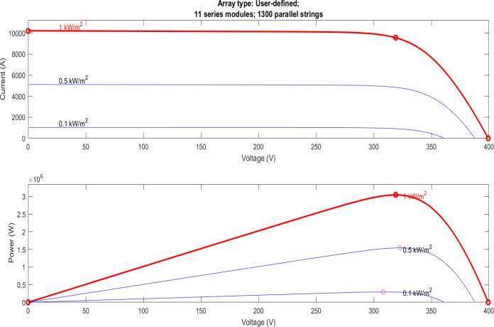
The Figure shows the graph of PV Array Voltage with respecttoTime. ThemaximumoutputvoltageofaPVarray of400Visobtained.Thesteadyoutputvalueofthevoltage of 350 V is obtained.The PV voltage initially increases linearly with respect to time and then it becomes approximatelysteady.
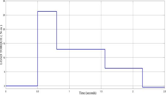
The Figure shows the graph of the Load Torque of the Induction Motor with respect to Time Initially,the load torqueis0N-mfortheinterval0to0.5.Thefullloadtorque is26.72N-mfortheinterval0.5to0.83whilehalfofthefull load torque is 13.36 N-m for the interval 0.84 to 1.67. Additionally,thequarterofthefullloadtorqueis6.66N-m fortheinterval1.67to2.16andthetorqueatzeroloadis0 N-mfortheinterval2.16to2.5.
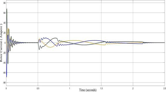
The Figure shows thegraphofRotor Current ofInduction Motor with respect to Time. TheThree-phase sinusoidal Rotor Current output is as follows: -At full load torque, the current is 10A. At half of the full load torque, the current is 5 A. At a quarter of the full load torque, the currentis2.5A.Atzeroloadtorque,thecurrentis0A
Electromagnetic Torque of Induction Motor with respect to Time.
The Figure shows the graph of the Induction motors Electromagnetic Torque with respect to Time. The Electromagnetic Torque output is as follows: - At full load torque,the electromagnetictorqueis 26N-m. At a quarter load torque, electromagnetic torque is 7 N-m. Electromagnetic torque is 15 N-m at 50% load. Zero load torqueequals0N-melectromagnetictorque.
In the presented simulation of 3-phase grid connected PV system a photovoltaic system that is able to produce the power of 2 MW of the power when irradiation and temperature given to the PV array is 1000 Watt/m2 (maximum) and 100 Watt/m2 (minimum) and 25οC is simulated. After using boost converter, the voltage of approximately1000VD.Cvoltageisobtained.ThePerturb and Observe algorithm of MPPT Methodis used for the simulation of this model. Three-phase voltage of the grid 350Vhasbeenattained.Afterthefiltrationofthevoltageas wellascurrentoftheinverteroutputof500Vand10000A of voltage and current of three-phase is obtained respectively. Itisobservedthat bydecreasingtheload the speedof the 3-phase induction motor increases and the motor torque decrease. And also, by decreasing the load thestatorcurrentandrotorcurrentdecreases.
[1] Kalimuthu Kumar, “A Sliding Mode Controller Based Boost Converter for Grid Connected Solar PV System” International Conference on Advance Computing and Innovating Technology in Engineering 2021 IEEE, pp. 1002-1005, doi: 10.1109/ICAC3N53548.2021.9725551.
[2] Manash Kumar Mishra, “Modified Proportional Resonant Current Controller with MPPT for Three Phase Single Stage Grid Integrated PV System” Indian InstituteTechnology(BHU)VaranasiIndia2020IEEE, pp. 3293-3297, doi: 10.1109/APEC42165.2021.9487359.
[3] Xiandong Zhou, “The Control Strategy of Harmonics Suppression of Photovoltaic Grid-Connected Inverter based on PI+MPR” IEEE 2019-20, pp. 1-5, doi: 10.1109/eGRID48402.2019.9092748.
International Research Journal of Engineering and Technology (IRJET) e-ISSN: 2395-0056
Volume: 11 Issue: 06 | Jun 2024 www.irjet.net p-ISSN: 2395-0072
[4] Kimball, “Modeling and Control of Three Phase GridConnected PV Inverter in the Presence of Grid Fault” Missouri University of Science and Technology 2018, pp.1-69.doi:10.1109/JPHOTOV.2017.277977.
[5] Banu, “Study on Three Phase Photovoltaic System Under Grid Fault” Proceeding of the 2014 International Conference and Exposition on Electrical and Power Engineering 2014 IEEE, pp. 1132-1137, doi:10.1109/ICEPE.2014.6970086.
[6] Sangita R. Nandurkar, “Design and Simulation of Three Phase InverterforGrid-connectedPhotovoltaic System” Proceedings of Third Biennial National Conference,NCNTE-2012,pp.80-83.
[7] Le Minh Phuong, “A Three Phase Grid Connected Photovoltaic System with Reactive Power Control” 2012 International Conference on Green Technology andSustainableDevelopment.
[8] Adriano Ruseler, “Three Phase Grid-Connected PV System withActiveand ReactivePowerControl using Dq0 Transformation” 2010 9th IEEE/IAS International Conference on Industry Applications. Haoran Bai, “A Research of Combined Multifunctional Three Phase Grid Connected Inverter and Active Power Filter for PV System” 2010 IEEE International Symposium on Power Electronic for Distributed Generation System, pp. 224-228, doi: 10.1109/PEDG.2010.5545852
[9] Adamidis, “Three Phase Grid-Connected Photovoltaic SystemwithActiveandReactivePowerControlUsing “InstantaneousReactivePowerTheory””International Conference on Renewable Energy and Power Quality 2010 IEEE, pp. 1086-1091, doi: 10.1109/ICELMACH.2008.4800248. Ravi Teja Poglaguntla, “Three Phase Differential Flyback Based Inverter for Photovoltaic Grid-Connected Applications” International Conference on Power Electronic, Smart Grid and Renewable Energy 2020 IEEE, pp. 1-6, doi: 10.1109/PESGRE45664.2020.9070272
[10]Mitra Mirhosswini, “Performance of Large-scale GridConnected Photovoltaic System under Various Fault Condition” The University of New South Wales Sydney, NSW, 2052, Australia, 2013, pp. 1775-1780, doi:10.1109/PowerAfrica.2012.6498626.
[11]Fanbo He, “Predictive D.C Voltage Control for Three Phase Grid-Connected PV Inverters based on Energy Balance Modelling” 2010 IEEE International Symposium on Power Electronic for Distributed Generation System, pp. 516-519, doi: 10.1109/PEDG.2010.5545820.
[12]T.Ostrem,“GridConnectedPhotovoltaic(PV)Inverter with Robust Phase Locked Loop (PLL)” 2006 IEEE, pp.1-5,doi:10.1109/TDCLA.2006.311434.
[13]M.VinayKumar,“ModelingandSimulationofaThree Phase Grid-Connected Photovoltaic System” European Journal of Molecular and Clinical Medicine ISSN 2515-8260 Volume-07 2020 IEEE, pp. 244-261, doi:10.1109/ICICCSP53532.2022.9862414
[14]Heydari, “Combined Modified P&O Algorithm with Improved Direct Power Control Method Applied to Single Stage Three-Phase Grid-Connected PV System” 9th Annual Power Electronic, Drives System and Technology Conference (PEDSTC) 2018 IEEE, pp. 347-351,doi:10.1109/TPEL.2022.3143951.
[15]Rym Marouani, “Sliding Mode Controller for BuckBoost D.C-D.C Converter in PV Grid Connected System” IEEE 2012 Unity of Research Analyze and Control System, pp.281-284, doi: 10.1109/MELCON.2012.619643.
[16]Abderrahi M, “Control and Management of GridConnectedPV-BatteryHybridSystemBasedonThree Level DCI” Proceedings of the 6TH International Conference on System and Control, University of Batna 2, Algeria 2017 IEEE, pp. 439-444, doi: 10.1109/ICoSC.2017.7958709
[17]Hongbin Wu, “Three Phase Photovoltaic Grid Connected Generation Technology with MPPT Function and Voltage Control” 2007 IEEE National Natural Science Foundation of China (NFSC) under Grant No. 50607002, pp .1295 -1300, doi: 10.1109/PEDS.2009.5385758.
[18]WuLibo,“ASingle-StageThree-PhaseGridConnected PhotovoltaicSystemwithModifiedMPPTandReactive Power Compensation” 2007 IEEE Vol. 22, No. 4, pp.47,doi:10.1109/TEC.2007.895461.