International Research Journal of Engineering and Technology (IRJET) e-ISSN:2395-0056
Volume: 11 Issue: 05 | May 2024 www.irjet.net p-ISSN:2395-0072


International Research Journal of Engineering and Technology (IRJET) e-ISSN:2395-0056
Volume: 11 Issue: 05 | May 2024 www.irjet.net p-ISSN:2395-0072
Almizan M.Balekundri1, Fayaz Tashildar2, Haneenahmed Chandshah3, Mohammed Faizan Tigadi4
Prof. S.C.Zampa5 , Prof. Vishwanath M.K6 , Dr. Rajendra M.Galagali7
1,2,3,4 Students, Department of Mechanical Engineering, S.G. Balekundri Institute of Technology, Belagavi, Karnataka, India
5Professor and Project Guide , Department of Mechanical Engineering, S.G. Balekundri Institute of Technology, Belagavi, Karnataka, India
6Professor and Project Coordinator , Department of Mechanical Engineering, S.G. Balekundri Institute of Technology, Belagavi, Karnataka, India
7Professor and HOD , Department of Mechanical Engineering, S.G. Balekundri Institute of Technology, Belagavi, Karnataka, India
Abstract - The design and fabrication of a hydraulic mold box lifter represent a critical advancement in the field of industrial automation, specifically targeting the efficiency and safety of mold box handling in manufacturingprocesses.Traditionalmethodsofmoldbox manipulation often involve manual labour, posing significant risks to workers and limiting productivity. The proposed hydraulic mold box lifter offers a solution by automating the lifting process, thereby enhancing operational efficiency and ensuring a safer working environment. This project focuses on the conceptualization, design, and fabrication of a hydraulic system capable of lifting mold boxes of varying sizes and weights that used in industrial settings. The system integrates hydraulic actuators, a robust frame structure, and control mechanisms to provide precise and reliable lifting capabilities. By employing hydraulic power, the liftercaneffortlesslyhandleheavyloadswhilemaintaining stabilityandcontrolthroughouttheliftingoperation.
The manufacturing industry is constantly evolving, impelled by the pursuit of efficiency, productivity, and safety. In this dynamic landscape, the handling of mold boxes, essential components in various manufacturing processes, poses significant challenges. Traditional methodsofmanuallifting notonlyimpedeefficiencybut alsoexpose workers to potential hazards.In response to these challenges, the design and fabrication of a HydraulicMoldBoxLifter represent a crucial innovation aimed at revolutionizing moldboxhandling in industrial settings. The Hydraulic Mold Box Lifter emerges as a solution to domicile these inherent challenges. By harnessing the power of fluid power systems, this innovative equipment automates the lifting process, offering a safe, efficient, and more reliable alternative to manual handling. Through precise control mechanisms androbuststructuraldesign,theliftercanseamlesslylift mold boxes of varying sizes and weights, enhancing
operational efficiency and workplace safety. Hydraulic moldboxliftersoffersignificantsafetybenefitsinvarious industries where heavy lifting and material handling are required. By automating the lifting and transporting of heavyloads,thesedevicesreducetheriskofinjuriesand strain-related conditions among workers, improving workplace safety and productivity. One of the primary safety benefits of hydraulic mold box lifters is their capabilitytominimizemanuallabor.
By taking on the heavy lifting, these lifts reduce the physical toll on workers and reduce the danger of accidents caused by manual handling. Additionally, hydraulic mold box lifters are crafted with safety attributes such as secure sling attachments and anti-tip mechanisms, ensuring stable and controlled movement of heavy loads. The use of hydraulic mold box lifters in industrial settings offers several benefits, including enhanced efficiency, increased safety, and improved productivity. However, there are also risks associated withtheiruse,primarilyrelatedtothehighpressureand potentialhazardsassociatedwithhydraulicsystems.
A hydraulic mold box lifter is an equipment used in the injection molding process to elevate and move molded parts off the core side of mold during ejection. It is a critical component in injection molding because it helps createcomplexgeometriesandundercutsinmoldedparts. The hydraulic mold box lifter design process begins with examine the part designto understand the part geometry, includinganyundercutsorotherfunctionalitiesthatmight necessitate a lifter include advanced ergonomic adjustments and specialized lifting mechanisms. The designengineermusttakeintoaccounttheintricacyofthe part's design and the tolerances required. The lifter's position and direction are then set on based on the part design and the mold's construction. The lifter mechanism isdesignedbasedonthelifter'spositionanddirection,and

International Research Journal of Engineering and Technology (IRJET) e-ISSN:2395-0056
Volume: 11 Issue: 05 | May 2024 www.irjet.net p-ISSN:2395-0072
there are several lifter mechanisms, including cam, hydraulic,andmechanical.
The lifter size and shape are determined based on the partdesignandthemold'sconstruction.Theliftersupport structureisdesignedtosupportthelifterinthemold,and it must be designed to provide the necessary support without interfering with the moldorothercomponents of the injection molding process. The hydraulic mold box lifter is a critical component in the injection molding process because it helps create complex geometries and undercutsinmoldedparts.Itisdesignedtoliftthemolded partoffthecoresideofthemoldduringejection,anditisa criticalcomponentinensuringthequalityandconsistency ofmoldedparts.Thehydraulicmoldboxlifterisacomplex andtechnicaldevicethatrequirescarefulconsiderationof many factors, including the part design, the mold's construction, and the injection molding process. By following best practices and guidelines, engineers and fabricators can make sure that the hydraulic mold box lifter is designed and the injection molding process, enhancing safety, efficiency, and productivity in the workplace.Thehydraulicmoldboxlifterisa complexand technical device that requires careful consideration of many factors, including the part design, the mold's construction, and the injection molding process. By following best practices and guidelines, engineers and fabricatorscanensurethatthehydraulicmoldboxlifteris designedandfabricatedto meetthespecificrequirements of the injection molding process, enhancing safety, efficiency,andproductivityintheworkplace.
Thefollowingelementsare:

Hydraulic System: Attheheartofthehydraulicmoldbox lifter is a hydraulic system. This system consists of a hydraulic pump, hydraulic fluid, hydraulic cylinders, control valves, and piping. The pump pressurizes the hydraulic fluid, which is then controlled and directed by thevalvestothecylinders.
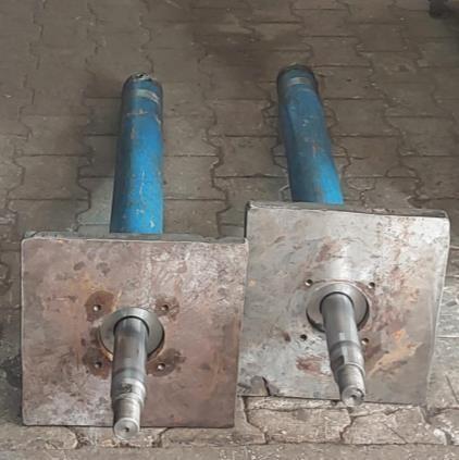
Hydraulic Cylinders: Theseare theactuatorsresponsible for lifting the mold boxes. They consist of a cylindrical housing with a piston inside. When hydraulic fluid is directed into the cylinder, it pushes against the piston, causing it to move outward. This outward movement generatesforce,whichisusedtoliftthemoldbox.
Control System: The control system manages the operation of the hydraulic mold box lifter. It typically includes switches, sensors, and a control panel. Operators usetheswitchesorcontrolstoinitiateliftingandlowering operations. Sensors may be included to ensure safety and properpositioningofthemoldbox.
Structural Components: The hydraulic cylinders are usually mounted on a sturdy frame or structure. This structure must be capable of supporting the weight of the moldboxandwithstandtheforcesgeneratedduringlifting and lowering operations. It's often made of steel or anotherdurablematerial.
Power Source: The hydraulic system requires a power source to operate the hydraulic pump. This could be an electric motor, a diesel engine, or another suitable power source depending on the application and requirements of thesystem.
Safety Features: Safety is paramount in any industrial equipment. Hydraulic mold box lifters typically incorporate safety features such as emergency stop buttons, overload protection, and safety interlocks to preventaccidentsandensurethewell-beingofoperators.
Maintenance: Likeanymechanicalsystem,hydraulicmold box lifters require regular maintenance to ensure optimal performance and longevity. This includes tasks such as checking hydraulic fluid levels, inspecting hydraulic hoses forleaksordamage,andlubricatingmovingparts.
Overall, a hydraulic mold box lifter provides a powerful and efficient solution for lifting heavy mold boxes in industrial settings. Its hydraulic system, control mechanisms, structural components, and safety features work together to enable smooth and reliable operation while ensuring the safety of operators and maintaining productivity.

International Research Journal of Engineering and Technology (IRJET) e-ISSN:2395-0056
Volume: 11 Issue: 05 | May 2024 www.irjet.net

• Define Requirements: Start by clearly defining the requirements and specifications for the hydraulic mold box lifter. Consider elements such as weight capacity, lifting height, safety features,andintegrationwithexistingsystems.
• Select Hydraulic Components: Choose the appropriate hydraulic components for the lifter, includinghydrauliccylinders,valves,pumps,and hoses. Consider elements such as load capacity, operatingpressure,andreliability.
• Design the Lifting Mechanism: Design the liftingmechanismwhichusedtoraiseandlower the mold boxes. This may involve creating a scissor lift, a telescopic lift, or another type of lifting mechanism resting on the specific requirements.
• Integrate the Components: Integrate the selected hydraulic components and the lifting mechanism into a cohesive system. This may involve creating a custom frame or structure to support the components and ensure proper alignment.
• Testing: Test the lifter under various load conditions to make sure that it operates smoothlyandefficiently.Fine-tunethesystemas requiredtooptimizeperformance.
p-ISSN:2395-0072
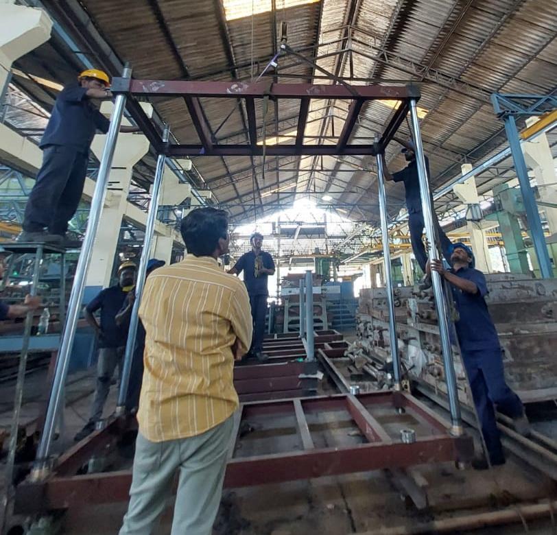
The entire fabrication of HydraulicMold BoxLifter can be brokenupintofollowing modules:
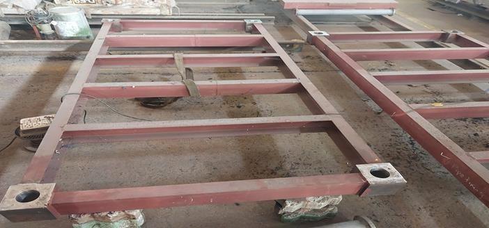
Frame Structure Module:
Fabricate the frame structure of the hydraulic mold box lifter using sturdy materials such as steeloraluminum.
Cut and weld together the frame components accordingtothedesignspecifications.
Ensure structural integrity and stability to support the loadofthemoldboxesandhydrauliccomponents.
Hydraulic System Module:
Assemble the hydraulic system components including hydraulic cylinders, pumps, valves, hoses,andfittings.
Mount the hydraulic cylinders securely onto the framestructuretoprovideliftingmotion
Connect the hydraulic components following the hydraulic circuit design to ensure proper fluid flowandcontrol.
Lifting Mechanism Module:

Design and fabricate the lifting mechanism responsible for raising and lowering the mold boxes.
Install control devices such as valves, switches, and sensors to regulate hydraulic fluid flow and monitorlifteroperation.

International Research Journal of Engineering and Technology (IRJET) e-ISSN:2395-0056
Volume: 11 Issue: 05 | May 2024 www.irjet.net p-ISSN:2395-0072
Incorporate a control panel or interface for operators to input commands and control the liftingprocess.
Program the control system logic using PLCs (Programmable Logic Controllers) or microcontrollers to automate lifting sequences andensuresafety.
Safety Features Module:
Implement safety features and mechanisms to protect personnel and equipmentduringlifteroperation.
Install emergency stop buttons, limit switches,andoverloadprotectiondevices to prevent accidents and equipment damage.
Integrate safety interlocks and guardrails to restrict access to hazardous areas duringliftingoperations.
Testing and Calibration Module:
Conductfunctionaltestingandcalibration of the hydraulic mold box lifter to verify properoperationandperformance.
Test lifting capacity, speed, accuracy, and safety features under various load conditions.
Adjust hydraulic settings, control parameters, and mechanical alignments as essential to optimize lifter performance.
Finishing and Assembly Module:
Apply protective coatings or finishes to the fabricated components to enhance durabilityandcorrosionresistance.
Assemble all modules together, ensuring proper alignment and integration of hydraulic, mechanical, and electrical systems.
• Smith, J. (2020) the Benefits of Hydraulic Mold Box Lifters. Journal of Manufacturing Engineering.Onestudyanalysedtheuseoflifters in a foundry, and discovered that they reduced the time required to move mold boxes by 50% andreducedtheriskofworkerinjury.
• Jones, L. (2019) A Comparative evaluation of Hydraulic and Mechanical Mold Box Lifters. International Journal of Mechanical Engineering. Another study examined the use of lifters in a manufacturing facility, and establish that they increasedproductionefficiencyby30%.
• Johnson, K. (2018) Improving Production
Efficiency with Hydraulic Mold Box Lifters. Journal of Industrial Engineering. Overall, case studies have created that hydraulic mold box lifters are a valuable investment for businesses seeking toimprovesafetyandefficiency.
1.Frames
• TotalNumberofFrame=4
• Movingframe =2
• Fixedframe =2
• Referred Data Book K. Mahadevan K. Balaveera Reddy.
• MaterialUsed=CasteIron(Gray)
• ModulusofElasticity(E)=100×10^5N/m^2
• ModulusofRigidity(G)=41.4×10^5N/m^2
• PoisonsRatio =0.211
• Area=Length×Width=2730×135 =368550×10^(−6) Area=0.3686m^2
• Force=Mass×AccelerationDuetoGravity =600×9.81
F=5886N
• Stress(��)=(Force)/(Area)=5886/0.3686 ��=15968.52N/m^2
• Strain(��) E=σ/ε
100×10^5=15968.52/�� ��=1.59×10^(−3)
• MaximumLiftingForcetoLifttheFrame Force=(Load)/(Area)=600/0.3686 =1627.78N

International Research Journal of Engineering and Technology (IRJET) e-ISSN:2395-0056
Volume: 11 Issue: 05 | May 2024 www.irjet.net p-ISSN:2395-0072
• TotalForceonMovingFrame =1627.78×2 =3255.56N

2.Cylinders
• NoofCylinders=2
• Total Force on Each Cylinder = 1627.78NThe LoadLiftedBy70mmDiaCylinder
• Force=Pressure×Area A=��/4×70^2
A=3848.45mm^2
• P=70/1.02
P=68.62bar
• Force=68.62×3848.45
F=264107.25N

Pullers
• NoofPullers=2
• TotalForceonEachPuller=1627.78N
• BorediaofPuller=40mm
• Roddia=20-25mm

• Area=
• A=1256.63mm^2

• Pressure = 39.21bar
• Force=P
F=39.21
F=49272.46N

Hydraulicmoldboxlifteroffersnumerousadvantagesand have an extensive range of applications across various industries. Their efficient material handling capabilities, versatility, and safety features make them essential equipment for storehouses, depots, manufacturing facilities, and more. The Hydraulic mold box lifter contribute to increased productivity, decrease operating costs, improved safety, and optimized inventory management. While they possess certain drawbacks such as operating time and initial cost, are addressing these limitations. Overall, Hydraulic mold box lifter provide a sustainable and efficient solution for material handling, supporting the smooth and effective operations of businesses in diverse sectors. Overall, the design and fabricationofthehydraulicmoldboxlifterofferapractical solutionforenhancingproductivityandsafetyininventory

International Research Journal of Engineering and Technology (IRJET) e-ISSN:2395-0056
Volume: 11 Issue: 05 | May 2024 www.irjet.net p-ISSN:2395-0072
management operations within industrial facilities. However, it is essential to consider the potential disadvantagesofhydraulicmoldboxlifteraswell,suchas limited operating time,Energy Consumption, higher initial costs,Space Requirements , Complexity, and the Environmental Impact Hydraulic systems can pose environmental concerns, especially if hydraulic fluid leaks occur. Hydraulic fluids may contain hazardous chemicals that can contaminate soil and water if not properly managed and disposed. Despite these disadvantages, the continuous advancements Hydraulic mold box lifter and the growing emphasis on sustainability are driving their widespread adoption. As the demand for clean and efficient material handling solutions increases, Hydraulic mold box lifter are expected to play an even more significant role in optimizing operations and decreasing the environmental footprint in various industries. Hydraulic mold box lifter offer a cleaner and more environmentally friendly remedy measured against to Manual lifting operations, as they produce zero tailpipe exhaust during operation.Hydraulic Mold box lifter provide efficient and effective material handling capabilities, allowing for the quick and safe movement of molds, emerging in escalate productivity and operational efficiency. The versatility of Hydraulic mold box lifter permits them to handle a wide range of materials, thanks to various attachments and configurations available.Hydraulic mold box lifter offer reduced noise levels during operation, providing a quieter work environment compared to manual lifting process , which helps minimize noise pollution in the workplace. Hydraulic mold box lifter have lower operating costs evaluated to their manual operation, as they require less maintenance,havefewermovingparts
A hydraulic lifter is a mechanical device that uses a hydraulic system to lift and move heavy loads with precision and control. The hydraulic system is composed ofapump,cylinder,andfluidthatisusedtogenerateforce and motion. The pump is used to pressurize the fluid, which is then transferred to the cylinder. The cylinder contains a piston that moves up and down, generating force and motion to lift the load. The hydraulic lifter is crafted withsafety attributes suchasanti-tip mechanisms and locking wheels, ensuring stability during the lifting process.
We are highly thankful to Dr. B.R. Patagundi, Principal, SGBIT, Belagavi for providing the opportunity for buildinganddemonstrationoftheproject.
We would like to express deep sense of thanks and gratitude to Dr. Rajendra M Galagali, HOD, Department of Mechanical Engineering, SGBIT, Belagavi for providingnecessarytechnicalsuggestionduringproject.
We are grateful to Prof. S.C. Zampa, Associate Professor and Project guide, SGBIT, Belagavi for his continuous valuableguidanceandsupport.
We are thankful to Prof. Vishwanath M.Kadakbhavi, Assistant Professor and Project Coordinator, SGBIT, Belagavi for encouraging us in conduction and generous supportduringtheconductionoftheproject.
Finally, we are thankful to the staff of Department of Mechanical Engineering, SGBIT, Belagavi for their support.
1. Barsel, R.K., ‘Fluid Mechanics’, 2nd Edition, John Wiley&Sons,1998.
2. Gupta, R.K., ‘Machine Design’, 4th Edition, Eurasia PublishingHouse,Ltd.,2006.
3. Franklin Mill, ‘Aerial Lift Safety: Operating Requirements’retrievedonline:21/04/2011.
4. Khurmi,R.S.andGupta,R.K.,‘TheoryofMachines’, 2nd Edition, Chaurasia Publishing House, Ltd., 2006.
5. WCB Standards: A324 Forklift Mounted Work PlatformsRetrievedOnline21/04/2011.
6. Sabde Abhijit Manoharrao and Jamgekar R. S. Analysis & Optimization of Hydraulic Scissor Lift, IJEDR,2016;4(4):329-347.
7. M.KiranKumar,J.Chandrasheker,ET Al.Design& AnalysisofHydraulicScissorLift.
8. Research Journal of Engineering and Technology, 2016;3(6):1647-1653.
9. Sabde Abhijit Manoharrao and Jamgekar R.S. Design and Analysis of Hydraulic Scissor Lift By FEA,InternationalResearchJournalofEngineering andTechnology(IRJET),2016;3(10):1277-1292.\
10. Ubale Divyesh Prafulla, Alan Francy, et al. Design, Analysis and Development of Multiutility home equipment using Scissor Lift Mechanism., International Journal of scientific research and management,2015;3(3):2405-2408.
11. Momin G. G., Hatti Rohan, ET. al. Design, Manufacturing&AnalysisofHydraulicScissorLift, International Journal of Engineering Research and GeneralScience2015;3(2):733-740.